@jackinnj:
While I was at it, I have also made epoxy of the preamp
that replaces feedback with an oven, but I don't like it.
It is not what I really want.
I thought the oven would work!
I can send you some 1K PTC resistors.
No, the oven works. But I really want feedback. The oven feels like
taking the backdoor in the dark.
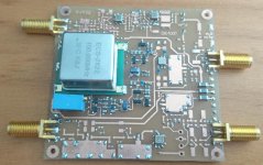
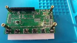
The oven uses a transistor as a sensor and another one as heater.
In the board picture, they are in the lower right in the middle of the
many SOT-23 FETs.
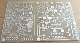
The board was meant to be made in China, bottom side is just
GND and some jumpers. Probably it does not make sense to
build on international logistics.
BTW I was surprised how fast the heat propagation was through an alu block.
I'll now bring the orange and the lemon tree from the living room into
the garden. There was no winter this year. I shoveled some snow
just once. Could have been sitting it out.
taking the backdoor in the dark.
The oven uses a transistor as a sensor and another one as heater.
In the board picture, they are in the lower right in the middle of the
many SOT-23 FETs.
The board was meant to be made in China, bottom side is just
GND and some jumpers. Probably it does not make sense to
build on international logistics.
BTW I was surprised how fast the heat propagation was through an alu block.
I'll now bring the orange and the lemon tree from the living room into
the garden. There was no winter this year. I shoveled some snow
just once. Could have been sitting it out.
Last edited:
... Makes me want even more to get a radio on HF, but I don't have anything working at the moment ...
You could also take a look at version 6 of VU2ESE's micro bitx.
All band HF with general coverage receiver, double conversion with first IF at 45 MHz, ring diode mixers. Strong user following. About $150 USD. I've been very tempted several times over the last few years ...
HF SIGNALS – The Home of BITX transceivers
What I need is mostly for the transmitting side, though I'd rather have a complete transciever so I don't have to worry about burning up a receiver's input if something's not right in switching between RX and TX. I have a Drake R8 with the VHF adapter that works fine. I just moved, I think my landlord will let me put up a wire to receive the 80 meter nets.
I have a Heath SB-101 that I bought 5 or 8 years ago that haven't powered up yet. I have TWO of the HP-25 power supplies for it, but I want to at least reform the PS caps and any electrolytics in the SB-101. Its only visible fault is missing the belts to go from the front panel controls to the driver and plate tuning caps. It even has VOX so I could just plug in my computer audio and do FT8.
I have a Heath SB-101 that I bought 5 or 8 years ago that haven't powered up yet. I have TWO of the HP-25 power supplies for it, but I want to at least reform the PS caps and any electrolytics in the SB-101. Its only visible fault is missing the belts to go from the front panel controls to the driver and plate tuning caps. It even has VOX so I could just plug in my computer audio and do FT8.
Misleading description, you didn't mention the 10 watt transmitter! Not a lot, but (with the right antenna) should get me heard throughout Atlanta and the suburbs.You could also take a look at version 6 of VU2ESE's micro bitx.
All band HF with general coverage receiver,
10 watts seems to be the de facto standard in kit rigs. Both my DZ Kit Sienna, and my Elecraft K2 are 10 watt kits, although a 100 watt PA is ( was ) available for each ... at a price. I just looked at the newest DZ Sienna XL, and the 10 watt transmitter for it is $2.25K USD option. Make it even $3K if you add the 250 watt PA.
Since you already have an R8, I expect it could be T/R switched and muted by a TR7, and the TR7 is an outstanding radio and not all that expensive. I have an R7 ( had several, actually ), but I've never had an R8. Should have got one when they were making them ...
Since you already have an R8, I expect it could be T/R switched and muted by a TR7, and the TR7 is an outstanding radio and not all that expensive. I have an R7 ( had several, actually ), but I've never had an R8. Should have got one when they were making them ...
Last edited:
I still have my FT505, probably not powered on for > 25 years.
Thanks Corona, the tranverter board exists and makes progress.
Some parts are missing and the IF filters must be calculated.
Those are really small balun transformers, who made them?
Are you going to be using SMD inductors in the bandpass filters?
I have not turned on my soldering iron, even though my line of work has mostly come to a standstill. Been learning simple CAD and hope to move on to PCB design with Nigel's program I bought a year or two ago.
Hi,
the transformers are from Pulse Engineering
CX2031, CX2041, CX2039, CX2047, 2074, 2147 etc
or MACOM
MABAES0060, MABAES0061 etc.
All available from Digikey or Mouser.
The tiny Inductors are Murata LQW18A series High Q 0603.
(those that look blue-ish.)
The shortwave inductors are 1210 or 18?? from Coilcraft
or EPCOS/TDK. They are not yet on the board.
Oh, I forgot the wideband 50 Ohm termination at least for the RX ring mixer
Cheers, Gerhard
Still haven't turned my soldering on, but may get to that later today after some yard work. If the T Storms come early, then I might get soldering earlier.
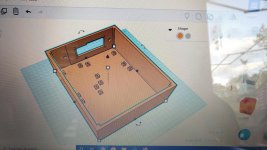
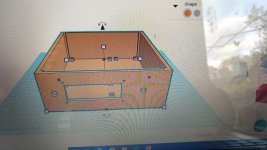
In the meantime, that funky little orange box with all the wierd angles has made me rethink the packaging of the device, if it ever gets finished. This is a Tinkercad box with mounting points for the QRP Labs frequency synthesizer and display, the SG-9, and three of the SMD prototype boards. The encoder for frequency change goes on the right side of the box because, after thinking about it, it seems like a more natural wrist movement when you are in a car. The idea here is this could slip between the console and the passenger seat for left hand drive cars. Maybe use a combination speaker/microphone for audio, so sound does not get blocked.
My metal box, which is mostly already cut and drilled for everything, except what would go in a control head, is about 190W x 260D x 60H mm. This plastic box with everything in it is about 165W x 200D x 60H mm, so quite a bit smaller. I could probably cut the height to 40 mm if I want or need to, maybe a bit less.
With support for that big panel opening, it should take about 218g of plastic, which is about $4 USD for the plastic from the local factory. Quite a bit cheaper than metal. It would take anywhere from 14 to 49 hours to manufacture, depending on the speed set on the printer. I tried to upload the .stl file or an .obj file of the model, but the system won't take those.
I really don't like metal working, it's my least favorite component of DIY, so anything I can shift to plastic, I'm going to try. It may or may not work.
Attachments
Last edited:
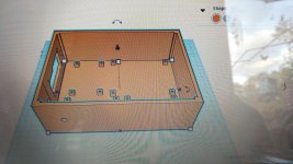
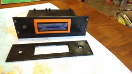
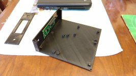
I "designed" a four piece modular case (top, bottom, front panel, and middle wrap around), and made it an arbitrary 170 x 170 m OD, thinking it would be more economical to make changes to smaller pieces as I move things around, and printed out a few pieces of it to see how things would fit together.
The AD8950 DDS and Si5351 frequency synthesizer require different front panel vertical sizes ( 46 and 40 mm, respectively ), requiring two panels and two wrap arounds to be drawn. You can't just scale them in a vertical dimension, because it distorts the mounting points. Instead of printing out the entire wrap arounds, I just sliced off the ends, and printed those to make the attachment points between all the pieces.
This was a useful exercise, and revealed a few flaws, notably, that measuring the internal projection of the LO's, and actually seeing them fitted in a chassis in relation to everything else, are a couple of different things. The interior projection of the LO's is such that in the 170mm case, I can only get one 50 x 80mm SMD board and the SG-9 fitted. In practice, this is not a big deal - I can just put mounting points on the top cover and hang more SMD boards from the cover.
I'm still waffling between having the radio split between one piece or two pieces with a control head, but I think I am leaning toward one piece.
Attachments
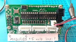
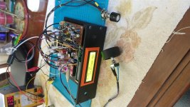
For anyone following, here is some essential information on how to actually use ( I hope ) one of these cheap AD9850 DDS VFO's in an actual radio:
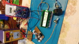
T/R switching is through an optocoupler (!); if you look at the first picture, the opto is the square device labeled PC817 near the upper left corner, and you can see I have soldered a wire to pin 2 of the device. GND pin 2 to switch between TX and RX.
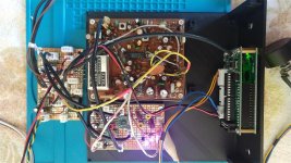
Unfortunately, as manufactured, the T/R switching just does not work. To make it work, refer to the second picture. On the right center of the picture, there is a row of 4 (four) 4.7K 0805 resistors. Remove and change the left most resistor to 10K.
It is essential to make the VFO know the radio is switching between RX and TX because this disables the RIT frequency shift when TX is engaged. Also, if you are using any TX offset for a particular mode, this tells the VFO to set the offset.
The waveform output of the device is abysmal in the upper frequency ranges, because the onboard amplifier is being overdriven. To cut the gain back above 20 MHz or so, refer to the first picture, and look at the top right center. You can see a jumper in place above a pad labeled 31M. There is another labeled pad, 21M, that is delivered with a jumper in place. Remove the 21M jumper, as shown in the photo.
These VFO's are advertised with an upper frequency limit of 40 to 55 MHz. 30 MHz is about all they will do. The clock is 125 MHz, it's adjacent to the optocoupler; I don't know if this is a crystal or a CMOS oscillator, but changing it might move the upper frequency limit up. I have not tried this.
The complete VFO draws 55 ma at 5 volts, and, as manufactured, a 78L05 supplies the operating voltage. This is completely unrealistic for an automobile voltage bus, and in practice you have to regulate the input voltage down to a voltage the 78L05 can take without overheating and shutting down. There is little to no room for a heatsink on this device, or for replacing it with a 7805. So what's the point, I just removed the 78L05 and put a jumper in its place. I labelled the board accordingly, because, well, I'm stupid, and sure as @#&$ you can bet I would hit it with +12 volts without the label ...
edit: once the regulator is changed, the contrast adjustment for the LCD will likely have to be readjusted ( mine did ). The adjustment is the little SMD trim pot below the 16 pin header in the second picture. You can't get to it with the display in place. Have fun.
Finally, those microswitches on the device are the cheapest crap imaginable, they have bugged me from day one, and one broke just from banging around in my box travelling to the lake house. So, I just clipped off the posts on the ones that were left, and felt immediately better. They are not necessary because they are brought out to the outermost white molex connectors on the back of the main board. The labels are pretty cryptic, but with some headscratching, they can be figured out. The center molex connector is for a keypad for direct frequency entry.
These are nice VFO's, they are very feature rich, and a terrific bargain imo.
Once you can actually make them work ...
T/R switching is through an optocoupler (!); if you look at the first picture, the opto is the square device labeled PC817 near the upper left corner, and you can see I have soldered a wire to pin 2 of the device. GND pin 2 to switch between TX and RX.
Unfortunately, as manufactured, the T/R switching just does not work. To make it work, refer to the second picture. On the right center of the picture, there is a row of 4 (four) 4.7K 0805 resistors. Remove and change the left most resistor to 10K.
It is essential to make the VFO know the radio is switching between RX and TX because this disables the RIT frequency shift when TX is engaged. Also, if you are using any TX offset for a particular mode, this tells the VFO to set the offset.
The waveform output of the device is abysmal in the upper frequency ranges, because the onboard amplifier is being overdriven. To cut the gain back above 20 MHz or so, refer to the first picture, and look at the top right center. You can see a jumper in place above a pad labeled 31M. There is another labeled pad, 21M, that is delivered with a jumper in place. Remove the 21M jumper, as shown in the photo.
These VFO's are advertised with an upper frequency limit of 40 to 55 MHz. 30 MHz is about all they will do. The clock is 125 MHz, it's adjacent to the optocoupler; I don't know if this is a crystal or a CMOS oscillator, but changing it might move the upper frequency limit up. I have not tried this.
The complete VFO draws 55 ma at 5 volts, and, as manufactured, a 78L05 supplies the operating voltage. This is completely unrealistic for an automobile voltage bus, and in practice you have to regulate the input voltage down to a voltage the 78L05 can take without overheating and shutting down. There is little to no room for a heatsink on this device, or for replacing it with a 7805. So what's the point, I just removed the 78L05 and put a jumper in its place. I labelled the board accordingly, because, well, I'm stupid, and sure as @#&$ you can bet I would hit it with +12 volts without the label ...
edit: once the regulator is changed, the contrast adjustment for the LCD will likely have to be readjusted ( mine did ). The adjustment is the little SMD trim pot below the 16 pin header in the second picture. You can't get to it with the display in place. Have fun.
Finally, those microswitches on the device are the cheapest crap imaginable, they have bugged me from day one, and one broke just from banging around in my box travelling to the lake house. So, I just clipped off the posts on the ones that were left, and felt immediately better. They are not necessary because they are brought out to the outermost white molex connectors on the back of the main board. The labels are pretty cryptic, but with some headscratching, they can be figured out. The center molex connector is for a keypad for direct frequency entry.
These are nice VFO's, they are very feature rich, and a terrific bargain imo.
Once you can actually make them work ...
Attachments
Last edited:
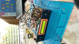
It's alive.
But not without a last bit of drama - all the SG-9 T/R voltages were caddywampus and had the board shut down; I traced this to a bad switching transistor. Replaced that. I had replaced it previously, but didn't have the correct part at the time. It's a 2SC945 and I have some with me, assuming a new Chinese "331" brand 2SC945 has much or even anything in common with a forty year old genuine one. Not sure if the second failure was due to my make do part, or if something else is going on. Anyway, the 331 part works, all the voltages are in the right places and switch correctly now, and all of the T/R, including mine, works properly.
I had to do a bit of work on the MC3340P attenuator. I'm not happy with it, it may be as simple as using a different pot, but I don't have any other panel mount pots with me. The sole surviving Radio Shack is about a 90 mile round trip from here, so not worth it to get one when I have a bunch back at home base. It may be that the '3340 just doesn't have enough attenuation, and will have to be discarded as a bad idea in this application.
The multiplicity of XH connectors that were an enormous PITA up to now - spent most of yesterday afternoon making cables - and look like Hades, were really appreciated when I could just plug / unplug everything.
The matching from the HP mixer to the crystal filter has got to be terrible, I'm guessing the filter is about 500 ohms, the chip output is 50, so I need to do something about that. I probably need some attenuation between the TX output of the SG-9 and the XVTR board. And of course a TX amp and a case.
I may work on the TX amp this afternoon; I have the here parts to do that. Listening to 20 meters for the first time in a long time right now ....
Attachments
To FFT transmitter power in excess of that which can be directly applied to the Red Pitaya inputs, do I build / buy a 50 ohm attenuator, and then attach the Red Pitaya between the output of the attenuator and the dummy load? And add the attenuator value back to get the magnitude of the spurious components?
If the RP input looks like 50 Ohm (should be, more or less), just put the attenuator
between the TX output and the RP. A 30 dB attenuator looks pretty good like 50 Ohms,
no matter what's on the other side. That would be 2 * 30 dB = 60 dB return loss even
if the other side is open. That would equal an excellent dummy load.
The attenuator must be able to burn all the power.
A 30 dB attenuator would reduce 1W to 1 mW.
73, Gerhard
Last edited:
The low end of 20 CW is sure hopping this morning.
I worked on the MC3340 attenuator and got it working the way I wanted, and then decided it was not needed since the radio will be one box in the passenger compartment, and the only thing in the trunk will be the PA. So I removed it.
Then I remembered I had not made any provision for turning the radio on and off. And I no longer needed the adjustable regulator. At this point I decided the whole control housekeeping board was pretty much a steaming pile of suck, so I mostly redid the whole thing.
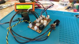
The easy way to turn it on and off would be a simple SPST switch to send 12 volts wherever needed. But I went back to home base for a few days, and the only pots I had with an SPST switch looked barely adequate for turning a transistor radio on and off. So I devised this Rube Goldberg scheme where the SPST switch becomes a grounding control line to switch the voltage regulators on and off by way of a PNP transistor switch. There are three regulators; a 78M05 for the front panel, a 78M12 for the yet to be built TX board, and a 78M12 for everything else. These are on the back of the control board, so the ground plane heat sinks them. The grounding control line will also make remote turn on / turn off of the PA practical, since it will be connected directly to the battery, and I fear the standing bias current ( edit: or tube heater current ) would be an unhealthy drain on the battery if the PA is not turned off when not in use. This also meant another metric buttload of XH connectors.
On the housekeeping board, starting at the top left corner and proceeding clockwise, there are the two conditioned outputs for the TX and RX LO; the three pin connector has the remote turn on control line for the external PA and the T/R switch line for the external PA. Immediately behind it is the DC input for the whole smack. Continuing clockwise, the three pin connector is regulated DC out to the TX board, and RF back in to the control board; the RX output to the transverter; the antenna input, and the speaker output behind the LM380. In the middle are the regulated DC output to the SG-9 board, and the three pin connector brings in T/R control line and low level audio from the SG-9. The three pin connector close to the LM380 is for the volume control; the two pin is the SPST on off switch, and the four pin is RF in from the DDS, and regulated 5 volt out to power it up. Whew.
The voltage regulators are switched on and off by S8550 pnp transistors.
I count four (4) birdies in the receiver - a warble at 14.139, and three very sharp spurs at 14.148900, 14.159600, and 14.62900. These are so sharp that one tuning step in either direction eliminates the spur. Only the spur at 14.159600 can be heard above the normal background noise with an antenna connected. With no antenna, you can hear some chuffing when the DDS is tuned, but atmospheric background noise completely masks this. edit: the DDS is a lot better in this regard than the frequency synthesizer - it was like being in a pet store ...
Speaking of antenna, right now it is a piece of wire tossed out the door, probably a foot or three short of a quarter wave on 20.
You might be able to see I made a matching network to match into the crystal filter on the SG-9, and added an attenuator to the TX output. I am going to move the latter over to the XVTR board; I don't like the way it looks on the SG-9 - there just isn't enough room there.
The to do list is getting shorter:
a TX board;
the case ( trivial non issue with the 3d printer; I printed out a few more pieces while I was back home );
undoing Dentron's SSB only wiring scheme to enable CW transmit;
A PA.
That's all I can think of at the moment.
The XH connectors are unsightly, an enormous PITA, and really are difficult to mount on that SMD proto board, but I must say it is nice to be able to plug and unplug everything in a minute or so to get a board free to work on. If anyone knows of a better suited connector, I would like to know of it.
The receive AGC that I had trouble with after I replaced all the electrolytic capacitors is working well. I would still like to have less gain. That NEC 575 audio chip on the SG-9 has about 50 dB gain, IIRC. The LM 380 is 34 ish. With an apparently pretty hot mosfet RF amp, an active RX mixer with a decent match into the XTAL filter, three stages of mosfet IF, and an active product detector, the receiver is pretty hot ... I guess I could try running an AGC line to the mosfet RF amp to cut it back some, or just turn it's gain down permanently.
I may look at the pin out of LM386-4 and see if I can easily sub it in to the control board, since it can be reduced to 20 dB, and will work with the existing mute circuitry for the LM380. Also nice would be some TX audio processing, maybe with these LM370 I have.
I worked on the MC3340 attenuator and got it working the way I wanted, and then decided it was not needed since the radio will be one box in the passenger compartment, and the only thing in the trunk will be the PA. So I removed it.
Then I remembered I had not made any provision for turning the radio on and off. And I no longer needed the adjustable regulator. At this point I decided the whole control housekeeping board was pretty much a steaming pile of suck, so I mostly redid the whole thing.
The easy way to turn it on and off would be a simple SPST switch to send 12 volts wherever needed. But I went back to home base for a few days, and the only pots I had with an SPST switch looked barely adequate for turning a transistor radio on and off. So I devised this Rube Goldberg scheme where the SPST switch becomes a grounding control line to switch the voltage regulators on and off by way of a PNP transistor switch. There are three regulators; a 78M05 for the front panel, a 78M12 for the yet to be built TX board, and a 78M12 for everything else. These are on the back of the control board, so the ground plane heat sinks them. The grounding control line will also make remote turn on / turn off of the PA practical, since it will be connected directly to the battery, and I fear the standing bias current ( edit: or tube heater current ) would be an unhealthy drain on the battery if the PA is not turned off when not in use. This also meant another metric buttload of XH connectors.
On the housekeeping board, starting at the top left corner and proceeding clockwise, there are the two conditioned outputs for the TX and RX LO; the three pin connector has the remote turn on control line for the external PA and the T/R switch line for the external PA. Immediately behind it is the DC input for the whole smack. Continuing clockwise, the three pin connector is regulated DC out to the TX board, and RF back in to the control board; the RX output to the transverter; the antenna input, and the speaker output behind the LM380. In the middle are the regulated DC output to the SG-9 board, and the three pin connector brings in T/R control line and low level audio from the SG-9. The three pin connector close to the LM380 is for the volume control; the two pin is the SPST on off switch, and the four pin is RF in from the DDS, and regulated 5 volt out to power it up. Whew.
The voltage regulators are switched on and off by S8550 pnp transistors.
I count four (4) birdies in the receiver - a warble at 14.139, and three very sharp spurs at 14.148900, 14.159600, and 14.62900. These are so sharp that one tuning step in either direction eliminates the spur. Only the spur at 14.159600 can be heard above the normal background noise with an antenna connected. With no antenna, you can hear some chuffing when the DDS is tuned, but atmospheric background noise completely masks this. edit: the DDS is a lot better in this regard than the frequency synthesizer - it was like being in a pet store ...
Speaking of antenna, right now it is a piece of wire tossed out the door, probably a foot or three short of a quarter wave on 20.
You might be able to see I made a matching network to match into the crystal filter on the SG-9, and added an attenuator to the TX output. I am going to move the latter over to the XVTR board; I don't like the way it looks on the SG-9 - there just isn't enough room there.
The to do list is getting shorter:
a TX board;
the case ( trivial non issue with the 3d printer; I printed out a few more pieces while I was back home );
undoing Dentron's SSB only wiring scheme to enable CW transmit;
A PA.
That's all I can think of at the moment.
The XH connectors are unsightly, an enormous PITA, and really are difficult to mount on that SMD proto board, but I must say it is nice to be able to plug and unplug everything in a minute or so to get a board free to work on. If anyone knows of a better suited connector, I would like to know of it.
The receive AGC that I had trouble with after I replaced all the electrolytic capacitors is working well. I would still like to have less gain. That NEC 575 audio chip on the SG-9 has about 50 dB gain, IIRC. The LM 380 is 34 ish. With an apparently pretty hot mosfet RF amp, an active RX mixer with a decent match into the XTAL filter, three stages of mosfet IF, and an active product detector, the receiver is pretty hot ... I guess I could try running an AGC line to the mosfet RF amp to cut it back some, or just turn it's gain down permanently.
I may look at the pin out of LM386-4 and see if I can easily sub it in to the control board, since it can be reduced to 20 dB, and will work with the existing mute circuitry for the LM380. Also nice would be some TX audio processing, maybe with these LM370 I have.
Attachments
Last edited:
Earlier I misstated the current draw of the DDS module - it is about 125 ma. No wonder its onboard 78L05 was struggling. The 78M05 seems to handle this without issue, I burned in the front panel circuits overnight at about 16 volts input to simulate a hard charging vehicle electrical system.
At first glance I think the DDS is better in the birdie situation than the Si5351 frequency synthesizer, and now with a working XVTR board and all the i/o connectors and the common five volt power source, it will be trivial to switch back and forth between the two to make a better judgment on this. They use the same size LCD, the DDS module is taller and deeper, so anything that will fit the DDS, will also fit the Si5351 synthesizer.
At first glance I think the DDS is better in the birdie situation than the Si5351 frequency synthesizer, and now with a working XVTR board and all the i/o connectors and the common five volt power source, it will be trivial to switch back and forth between the two to make a better judgment on this. They use the same size LCD, the DDS module is taller and deeper, so anything that will fit the DDS, will also fit the Si5351 synthesizer.
- Home
- Member Areas
- The Lounge
- No RF gear here?