I have made a preamp for 432 this weekend. ...
I haven't turned on my soldering iron since my last post. Historic rain and flooding here this Spring; now that everything is starting to dry out, I've been sitting on a mower.
I got a PCB design program from one of the members here, but haven't had a chance to play with it. I quit making boards because I hated drilling them, but that won't be as big an issue with SMD/SMT.
I have put a fan on the Red Pitaya - a $1.50 USD device from eBay, 30 mm, made for a Raspberry Pi. I have it set to pull air through the case and this seems to work very well. I have Charly 25 installed on one computer, but haven't tried to link it to the RP yet.
I think when I am ready to play with SDR on the RP, instead of doing a block conversion, I'll use the RP as a 45 MHz fixed frequency IF and RF source, and use the Si5351 as the tunable local oscillator to mix to that IF. At this point, I have a fair amount of practical understanding on how to get to 45 MHz from HF with simple mixers and xtal filters, and how to use the Si5351, so should not be too difficult. A bonus is that I will have a real knob for tuning, instead of a mouse.
... My 432 MHz preselector filter was easy. I took a SAW filter from EPCOS/TDK or whoever owns that company this week. ...
I know nothing about SAW filters, so haven't thought about how they could be useful to me. I was looking on eBay and found this filter:
EPCOS X6863D 23.4MHz SAW Filter B39234-X6863-D100, BW=1.9MHz, SIP5D, Qty.10 | eBay
The part number traces out as 23.4 MHz, even though some of the listing text says 24.4. This looks like it could be a good bandpass filter for my LO, since injection is at 23.0-23.4 MHz. I have to attenuate the LO anyway, so attenuation inside the passband is a bonus feature.
This seller has bazillions of good surplus parts, cheap. I have bought 45 MHz filters from him.
I've been sitting on a mower.
I've been fixing mine again....and again. The last surgery involved replacing a cylinder head with an Ebay sourced used part. I believe that I found the source of the overheating since I pulled the remains of three rather crispy mice out of the area where cooling air exits the bottom of the engine.
I previously noted a bent exhaust pushrod caused by the valve guide migration. I pounded the guide back in and straightened the bent pushrod. The mower ran fine for two 1 acre jobs and the problem returned. Some more work with a hammer made it live enough for me to wait for a $55 used head which I installed last week. In doing so I noticed that the intake pushrod was bent, and I didn't have one, so it was hammer time again. Mowed the yard with the replacement head and hammer straightened pushrod, and ordered a new one.
The rain that started in Texas last week has been here flooding out people for several days, and isn't leaving soon. The new pushrod is still in its package.
I was looking on eBay and found this filter:
The spec sheet has been removed from the listing by Ebay. Saw filters with 5 and 6 MHz bandwidth for TV use have been around for over 20 years although I have never seen one this low in frequency. They're usually in the 35 to 70 MHz range. They all have a LOT of insertion loss compared to "normal" SAWs, usually 15 to 20 dB. If you have enough gain to deal with this, it's a good choice, but.....20 db of loss in the filter makes it more important to consider the board layout and shielding. If the filter has 50 db of out of band rejection and 20 db of loss, your layout needs to have 70 db of input to output isolation around the filter to achieve the 50 db rejection. This is not too difficult at 20 something MHz, but isn't trivial at 2 GHz.
This seller has bazillions of good surplus parts, cheap. I have bought 45 MHz filters from him.
I got some of the same 45 MHz Filters and a whole bunch of other stuff from him over the years. He has a few dozen or so different "test boards" to fit the usual types of RF chips and SAW filters at reasonable prices. I have several different versions of them built for selectively filtering and amplifying the various cellular frequencies for use in testing an LTE device I'm working on.
...The rain that started in Texas last week has been here flooding out people for several days, and isn't leaving soon. ...
It got pretty bad here.
The first ( bad ) pic is from my car - the base of the billboard seen through the window is normally about 16 feet above dry ground. This road was closed a few hours later.
Second pic is a few hundred yards from a property I own across the line in Oklahoma. The river is supposed to be miles from here ...
Third pic is a town - I think that rooftop sticking out of the water is a school or city hall. This is from another closed road into town; I walked it out until it became underwater.
When I got done mowing Wednesday, I tossed a drive belt off my zero turn. Refitting this is a miserable task. I had been doing power slides with it ( yes, with sufficient stupid, and enough horsepower, you can power slide a zero turn ) but it tossed the belt as I was putting it on the trailer.
Attachments


We haven't had that kind of standing water here, just newly formed rivers running where streets used to be. Not much of it has made even the local TV news, but there are several videos on Facebook, one with an unoccupied car being swept down the street by the water.
The creek behind our house runs from the Ohio rive,r past us, then all the way into Pennsylvania (20 miles). The sun can be shining here, but a strong storm or snow melt 10 miles to our east can flood our backyard. So far that hasn't happened in this storm series.
The creek behind our house runs from the Ohio rive,r past us, then all the way into Pennsylvania (20 miles). The sun can be shining here, but a strong storm or snow melt 10 miles to our east can flood our backyard. So far that hasn't happened in this storm series.
It was Field Day this weekend, and since we had more frog strangling rain all weekend, I elected to operate from the house. Which revealed my SteppIr controller still has residual damage from last years lightning trauma. Something is drawing way too much current in the box - it has an LM2596 buck regulator that pulls down the 33 ish volts to 5 volts, and something is drawing enough current to severely overheat the little inductor in its output line. I get hash on the radio when the motors are supposed to be running, but the driven element seems stuck at around 16 MHz. So maybe only the director is running. I've replaced the cratered motor driver chips, checked all the passives, and the microprocessor seems OK, but I cannot get a schematic for the thing, so I guess I'll have to call their tech support and see if they have any suggestions.
Or pony up for a new $$$ box. Which - wild guess here - will probably be the suggested fix.
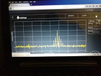
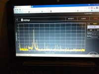
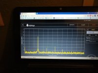
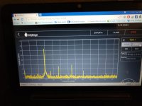
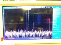
Otherwise, it has been suggested to me that the Hantek FFT's could be deceiving me. I brought the Si5351 thing down to the office and looked at it with the 14 bit Red Pitaya. And there are some significant differences to be seen.
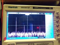
The first pic is 5.2 MHz, between 4 and 6 MHz. This shows a lot of crud, more or less, mostly more, consistent with the Hantek FFT.
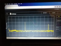
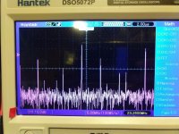
The second pic is 23.2 MHz - those vexing spurs around 15 -16 MHz are absent. Very inconsistent with the Hantek FFT.
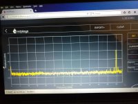
The third pic is 59 MHz. This is more or less, mostly more, consistent with the Hantek FFT.
One possible variable is the power supply for the Si5351 device. I was using a wall wart at home, and here at the office, because all my linear supplies were / are being used for other bits of the apparatus. Here at the office, I had difficulty getting a good wireless connection to the RP, which I traced to interference from the Lenovorola wall wart the Si5351 was plugged into. Switching to another wall wart fixed this. So, to state the obvious, not all wall warts are created equal. I think I need to build a 5 volt linear supply for the work bench, just to eliminate bad power on the bench as an unresolved variable.
So, I'm not sure what to make of this, other than that the RP seems to be a neat device.
Or pony up for a new $$$ box. Which - wild guess here - will probably be the suggested fix.
Otherwise, it has been suggested to me that the Hantek FFT's could be deceiving me. I brought the Si5351 thing down to the office and looked at it with the 14 bit Red Pitaya. And there are some significant differences to be seen.
The first pic is 5.2 MHz, between 4 and 6 MHz. This shows a lot of crud, more or less, mostly more, consistent with the Hantek FFT.
The second pic is 23.2 MHz - those vexing spurs around 15 -16 MHz are absent. Very inconsistent with the Hantek FFT.
The third pic is 59 MHz. This is more or less, mostly more, consistent with the Hantek FFT.
One possible variable is the power supply for the Si5351 device. I was using a wall wart at home, and here at the office, because all my linear supplies were / are being used for other bits of the apparatus. Here at the office, I had difficulty getting a good wireless connection to the RP, which I traced to interference from the Lenovorola wall wart the Si5351 was plugged into. Switching to another wall wart fixed this. So, to state the obvious, not all wall warts are created equal. I think I need to build a 5 volt linear supply for the work bench, just to eliminate bad power on the bench as an unresolved variable.
So, I'm not sure what to make of this, other than that the RP seems to be a neat device.
Attachments
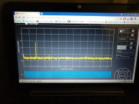
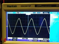
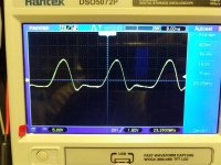
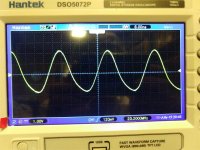
When running the spectrum analyzer program ( two channels 0-63 MHz ), the Pitaya can also do two channels of AF/RF output.
Here is output channel 2; 0.1 volt, 9 MHz, input probe /10, looped back into input channel 1. The outputs will go up to 1 volt, presumably to 63 MHz.
Sure looks it will be a good kitchen table piece of test equipment, in addition to the SDR capability. Lot of bang for the ( insert appropriate unit of currency here ).
Attachments
Last edited:
Played some more with the RP this afternoon.
I looped the signal generator output back in to the input, and the signal generator (sine wave) function has a maximum output of +7 dBm, with a cut off frequency of 50 MHz. Signal purity degrades quite a bit after about +2 dBm. I only looked at the sine wave function.
I used the RP sig gen at 9 MHz to sub for the IF input, and took a look at the tx mixer output. These look generally consistent with the Hantek FFT's, but the Hantek FFT displays in simple dB ( I think, I guess I'll have to RTM ) while the RP is displaying dBm.
Left to right, they are high side injection, no probe attenuation; high side injection, probe divide by 10 ( I always use divide by 10 on the Hantek ); and low side injection, no probe attenuation.
Attachments
") Gerhard
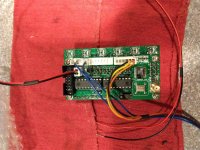
GerhardI hooked up the cheap eBay AD9850 DDS module last night.
It comes with nothing, no instructions, no pigtails, no encoder, so I had to spend a bit of time hooking that stuff up, which kept me from being able to spend much time playing with it.
I don't know what the correct voltage is, but this one is best at about 8 VDC. Below that, you get output, but can't see the display. Above that, the display will fade after a minute or so.
These are advertised as 0-55 MHz, but this one has only a 125 MHz clock chip, and the useful upper limit maxes out at about 41 MHz, or so. So, it should really be advertised as 0 - 40 Mhz.
This one has kind of an interesting feature, in that as the the encoder is spun faster, the tuning rate advances, much like a real radio. I installed a non detent encoder on this ( because it is what I had in stock ) so it has a nice feel, but for mobile use, I think a detent encoder will be a better choice.
There is an RF board on the back of the DDS board. This one has a non descript SOT-89 chip that just says "RF" on it. THe gain is set wrong for frequencies around 20 MHz, as shown in the FFT. There is a jumper that can be removed to turn the gain down in this range, but I have not played with that, yet.
FFT's attached in the 5 MHz and 23 MHz range ( low and high side injection for converting 14 MHz to 9 MHz ) and you can see that the 23 MHz signal is about ten fold stronger than the 5 Mhz side, and horribly distorted as a result. 5.X Mhz looks good, only harmonics of the fundamental show up on the FFT.
Attachments
We haven't had that kind of standing water here, just newly formed rivers running where streets used to be. Not much of it has made even the local TV news, but there are several videos on Facebook, one with an unoccupied car being swept down the street by the water.
The creek behind our house runs from the Ohio rive,r past us, then all the way into Pennsylvania (20 miles). The sun can be shining here, but a strong storm or snow melt 10 miles to our east can flood our backyard. So far that hasn't happened in this storm series.
George - you would find McCulloughs book “Pioneers” to be very interesting - your neck of the woods from the 1770s to 1850’s.
Interesting -- I remember going outside and just staring into the sky after this was over.
I don't think we got a color TV until 10 years afterward!
Unified S-band - Wikipedia
References 1 and 4 are pretty interesting reading. The command module ran a 20 watt carrier.
I recall reading that some Ham was able to pick up one of the lunar backpacks with a giant corner reflector antenna - they were in the UHF aero band - 273 something MHz, IIRC. Pretty good DX.
edit: W4EJA
Eavesdropping on Apollo 11
Last edited:
I don't think we got a color TV until 10 years afterward!
I had the only color TV in the neighborhood. It was a 1957 vintage Emerson (RCA built) that I had rebuilt with a 60's vintage all glass CRT. My bedroom was the old garage with some carpet (bare concrete, bare feet, and hot chassis electronics DON"T mix). There were 30 or so people stuffed into it in the middle of the night to watch that first live color broadcast from the moon.
I recall reading that some Ham was able to pick up one of the lunar backpacks
There was an older ham who had built a large dish antenna with lunar tracking to receive the LEM to Earth transmissions. He had recorded them to analog tape and he would play them to an audience in a forum meeting at the Dayton hamfest in the early 2000's. His completely independent transcription of the events helped dispel some of the "it never happened" conspiracies. Don't know what happened to it all when he passed.
Interesting -- I remember going outside and just staring into the sky after this was over.
I don't think we got a color TV until 10 years afterward!
We in southern Germany can stare tonight, too. 2/3 Lunar eclipse.
BTW. I have not forgotten you. I have built up the first 3 pieces; the post
amplifier was oscillating. That was coupling over the analog mux, I could
fix that with isolation resistors. Expect mail early next week.
Gerhard
- Home
- Member Areas
- The Lounge
- No RF gear here?