Hi W5JAG,
With my very limited experience in all things RF, I would say, absolutely! That's why good equipment design puts circuits inside shielded enclosures and uses shielded cables as well. In really good stuff they use hardline. Cable a lot like plumbing in that it isn't flexible and is in fact a pipe.
Any circuit element can be made unstable if the circuit doesn't follow normal practices for that application. Others here can provide much better guidance than I can.
-Chris
It's not best practice, no doubt about it, but that's not it.
I rerouted that lead, tried some series resistance in the output, fiddled with the decoupling, without any improvement.
I can kill the oscillation by dropping the VCC, but that's about all it seems to respond to at the moment.
I can get the needed gain with an IF amp at 45 MHz, but I'm not sure the mixer chip is quiet enough to be usable at HF without something low noise in front of it. It is looking like I'll have to try that and see.
In another setback, I won an eBay auction for a KVG 10.7 MHz LSB filter, only to have the guy tell me he has misplaced the filter. eBay, sheesh.
Win W5JAG
When not faulty, yes. Degrade the oxide film and things can change.Wavebourn said:Aluminium - oxide capacitors (AKA electrolytics) have conductors separated by an oxide film.
False assumption. As a general rule you can use a particular technology as a useful oscillator at higher frequencies than it can work as a useful amplifier. This is because a useful amplifier needs to have some degree of in-out isolation, lowish noise, sufficient gain to actually improve the noise figure etc. This is why early use of a technology for higher frequency reception usually has to omit an RF stage; we can usually make oscillators and mixers before we can make amplifiers.w5jag said:I figured that if an MPF102 would oscillate satisfactorily at 36 MHz, it could also buffer at that frequency.
Last edited:
Yes, as Tubelab said, maybe not in these words, the circuits that do not work are the ones that teach, frustrating as it may be. Stuff that works right off the bat can be nothing more than dumb luck. If this board stays as a double conversion setup with 50 ohm mixers, now that the oscillator / buffer works properly, it will probably be replaced with an LM375.
The perfboard is easy to work with, and there are some other circuits I want to play with, so not sure how much effort I want to put into this one. There are a few more things I want to try to see if I can get this to work, but I may move the MMIC to a gain stage in between the two mixers, and if it is stable there, then try that setup with the Mizuho board to see if it is quiet / sensitive enough without an RF preamp ahead of the first mixer.
There are still a lot of things I want to try, so even if this setup can be made to work right, there is a good possibility it will be torn back down to parts to try out some other stuff.
I tore down that board with the diode DBM's a while back, so I have those, and a few leaded broadband transformers, and now some decent enough leaded RF FET's. Maybe even some vacuum tube stuff. At a hamfest a few years ago I got some NOS J.W. Miller RF transformers; I think I have enough to make a single band, single conversion, tube transverter for the Mizuho IF board.
Win W5JAG.
I figured that if an MPF102 would oscillate satisfactorily at 36 MHz, it could also buffer at that frequency.
It should work fine since it's called a VHF part and S parameters are given out to 900 MHz. It is however nowhere near 50 ohms, so some impedance matching on both ends are needed for gain.
These days it's possible to use a "connect the blocks" methodology far into the GHz region, but it's best to stick with 50 ohm blocks to get a basic design operational. Then you can swap out blocks one at a time for non 50 ohm blocks if a better part is available. This makes impedance matching needed on one block at a time.
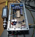
Purchased one of these:
0.1-2000MHz RF Wideband Amplifier 30dB low-noise LNA Broadband Module Receiver 902204774582 | eBay
I'm guessing the chip is the HP INA-02186. Obsolete, but finding a second life on these inexpensive boards. 2 dB NF well past the 70 cm band.
Can't beat the price. I'll want to remove those SMA connectors.
Win W5JAG
Attachments
I like these chips for general purpose gain blocks. 50 ohms on each end, near zero noise figure, very good IP3 performance, and capable of over 100 mW of power output if needed. They are a bit hungry for battery powered devices though. They are the same chip in different packages. The SOT89 is more user friendly for DIY.
Mouser has them in stock.
Data sheet too big to enclose, download from Mouser
Quorvo SPF5122Z and SPF5189Z
SPF5189Z Qorvo | Mouser
SPF5122Z Qorvo | Mouser
Mouser has them in stock.
Data sheet too big to enclose, download from Mouser
Quorvo SPF5122Z and SPF5189Z
SPF5189Z Qorvo | Mouser
SPF5122Z Qorvo | Mouser
Not sure that SOT-89 would fit on that SMD protoboard I have been using.
I see SOT-89 / SOT-223 to DIP adapters, but I wonder if a high gain MMIC can be stable when installed that way? I did try one other MMIC, an NXP BGA2817 SMD device installed on an adapter board, and it was totally unusable - pure noise. So bad I didn't even try to debug it; just put the upc1651 in it's place, since they had previously been unconditionally stable, even in a sketchy installation.
I still think the issue I am having now is not impedance matching, but just plain poor grounding, or poor decoupling, or a combination of both, so I am probably going to throw some more time at it and see if the problem can be solved just on general principle, even though the device is probably too noisy for an RF stage, even at HF.
Win W5JAG
How do you deal with soldering the SPF5122Z
I made the test PC boards when I was still working at Motorola so they had solder mask and a good footprint for the little SMD part. We had access to solder paste in syringes so I put a little dot on each pad, then dropped the chip in place on top of the solder paste. I did the same with all other small parts on the board, chip caps, resistors, inductors, and the like. Once all of the small SMD parts are sitting on the solder paste covered pads, I reflowed the board. Larger parts like SMA connectors are then hand soldered after the reflow.
I found two ways to reflow the parts that didn't require special equipment. My preferred method for small parts like this is simply to cook the board from the top with a heat gun, the kind you get from Home Depot for stripping paint. I set the PC board on an aluminum tray which is sitting on a kitchen hot pot pad. It takes some practice to learn how much heat to use to avoid frying the board. It is best to practice on some junk boards removing parts first. Once the board has reflowed, remove the heat and let it cool.
If the board has some larger parts mixed in with small stuff I cook these from the bottom on a hot plate. Place the board with all the parts in the solder paste on the heated hot plate allow all parts to reflow, then pick the board up with a suitable grabber (I use Vice Grips) and transfer it to a cold heat sink for cooling. If there are some large parts with some thermal mass (RF power transistors or modules) it helps to hit them from the top with the heat gun while cooking the entire board from the bottom on the hot plate.
The idea is to heat the SMD parts up to reflow temp as quickly as possible, let the solder completely reflow, but leave the components at the elevated temp for the shortest possible time.
When using the heat gun method on a large board I will do a small section at a time (1 to 2 Sq inches). You just need to be careful not to bump any parts when doing a subsequent section. Your heat gun needs to flow a minimum amount of air to do the job, otherwise it can blow parts off the board.
My boss got me a Hakko SMD rework station which I just used as a small heat gun without any of the attachments. It had variable heat and airflow, so I could reflow about an inch of board at a time without blowing parts off. Its main attribute over the heat gun was light weight. A few years ago when my hands were steadier I could change 30 X 60 (0603) parts with a heat gun, a pair of tweezers and some liquid flux. My hands are too shaky for that today.
Solder paste and flux used to be available from Amazon, but I haven't bought any in a few years. The hot plate I use did come from Amazon. It is a cheapie branded "Aroma." I set a 1/4 inch thick piece of aluminum (about 6 X 6 inches) on top of it let it heat until solder melts quickly, then set the board to be reflowed on top of it. Once the solder reflows (about 1 minute), I pick up the aluminum plate with PC board in place and set it on a large finned heat sink. It's usually cool enough to touch in about 5 minutes. Stay away from lead free solder. It takes too much heat and is picky about cook time.
Hi George,
Thanks for that. I've had limited success using liquid solder flux, thin leaded solder and a mid-sized screwdriver tip. The flux will draw the solder in most of the time. If it doesn't, all you can do is add flux and try again. It is frustrating this way.
-Chris
Thanks for that. I've had limited success using liquid solder flux, thin leaded solder and a mid-sized screwdriver tip. The flux will draw the solder in most of the time. If it doesn't, all you can do is add flux and try again. It is frustrating this way.
-Chris
In the good old (SMD) days the solder paste contained sufficient flux that was soluble in a suitable solvent. Even before ROHS and "getting the lead out" the solvents became under attack. We originally used a Freon based solvent, but that was deemed bad. We then went to a terpene based solvent which made the entire factory smell like an orange grove. Eventually it was banned too. Next was some synthetic stuff. All the while, us hand solderers could clean the boards with alcohol. Often the solder itself contained enough residual flux that additional flux was not needed for a one off parts change. Repeated parts swapping on the same pads would require a bit of flux once the solder didn't look shiny.
Then came the no wash flux. It worked sort of OK, but dried up into a clear hard residue that was useless if the board ever needed rework, hence the liquid or paste flux. I had a bottle of Kester rosin based paste flux that worked great, but was banned from the factory for some reason. They tried to confiscate it all from engineering, but we didn't work on shipping product, so they never got to us.
It worked great for reflowing old solder, even the no lead crap if you got it hot enough. The liquid flux we had seemed to have an alcohol base which would dry up within an hour, so you constantly had to scrub down the board and reflux it if you were changing a lot of parts. Too much flux, especially paste flux will float an IC chip when the solvent in it boils, so use just enough to wet the solder.
I was the guy developing prototypes, test boards, and EVB's, so changing lots of parts was my job.
We had done a board change on a two way radio prototype and our build on the automated line was over a week out, so I took and old radio that worked, and a new blank board, some headphones, some tunes and sat down in a corner of the lab. About 10 hours and 400 parts later I had a working radio with the new board in it. That was about 20 years ago, so my hands and eves worked much better. Only screwed up a few parts, and did grab new chips to replace those in BGA. We had a girl who could re-ball the BGA's with a fixture that had lots of tiny holes, but it's easier and more reliable to use new chips if they are available.
I have a small vapor phase machine, just enough for 1 double EuroCard (160 * 233.4mm).
It is not very automated, but it makes sure that the Galden vapor is not overheated; that
would be quite toxic. I have not much experience with it, but in the close future there
will be some BGAs that definitely need it. The producer is a ham, too, so I got a
nice discount.
I solder most things with a Metcal MX5200 and the ultrafine tips; they have a lot of
power in spite of the small tip. And I also have a Chinese Aoyue 852 hot air station
that I'm positively surprised of. I first put it into the garage for a month because it
smelled like an exploded chemical plant. It works quite some years by now.
I solder everything under a stereo microscope, probably from Russia.
Once you are over 60, there's no alternative.
You should really get some perf board with a copper mesh on the upper side;
suddenly you get a defined ground layer.
My boards are usually quite small with one layer + GND layer. That makes them
easy to etch. I use pre-sensitized Eurocards (100*160mm) made by Bungard,
0.5mm thick, Copper thickness is only 17 um, there will be no underetching and
the structure size is good enough for 6 mil/6mil design rules.
Computer output is a .pdf drawing, printed to a foil on the laser printer and then
via contact copy to the board material. I use a face tanner (?) as a UV source,
10 min. through a glass plate. Developing in NaOH takes a minute, etching in
Na- or ammonium persulfate 10 minutes. From computer to first soldered smd
parts can be less than 2 hours.
I combine my system then from these small stamps; inverting or noninverting
op-27-like OpAmps, mixers, regulator are usually availble from previous projects.
The new stamps never fill the EuroCard, so I replicate them until the board is
full for later consumption. I/O of the tiny boards is on 100 mil centers, that
fits neatly to the shielded perfboard Eurocard.
BTW I have heard that the main attraction of the MPF102 is price; it would be
that what is left when everything with interesting features has been selected out.
Maximum spread of data.
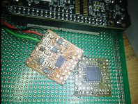
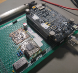
The first pic is a preamp that is quite close to that in Art Of Electronics V3,
70 pV / rtHz, but the input impedance is quite low.
The 2nd and 3rd is a digitizer stamp with a LTC2500-32 ADC, 2 LT3042 pos.
regulators, fully differential input amplifier with a neg. regulator and LT6655
voltage reference. The stamp with the Xilinx Coolrunner makes the sample clock
and collects the leftover digital stuff.
In the rear is a Beaglebone Black that will collect the data and do the FFTs
and network interface.
Cheers, Gerhard
It is not very automated, but it makes sure that the Galden vapor is not overheated; that
would be quite toxic. I have not much experience with it, but in the close future there
will be some BGAs that definitely need it. The producer is a ham, too, so I got a
nice discount.
I solder most things with a Metcal MX5200 and the ultrafine tips; they have a lot of
power in spite of the small tip. And I also have a Chinese Aoyue 852 hot air station
that I'm positively surprised of. I first put it into the garage for a month because it
smelled like an exploded chemical plant. It works quite some years by now.
I solder everything under a stereo microscope, probably from Russia.
Once you are over 60, there's no alternative.
You should really get some perf board with a copper mesh on the upper side;
suddenly you get a defined ground layer.
My boards are usually quite small with one layer + GND layer. That makes them
easy to etch. I use pre-sensitized Eurocards (100*160mm) made by Bungard,
0.5mm thick, Copper thickness is only 17 um, there will be no underetching and
the structure size is good enough for 6 mil/6mil design rules.
Computer output is a .pdf drawing, printed to a foil on the laser printer and then
via contact copy to the board material. I use a face tanner (?) as a UV source,
10 min. through a glass plate. Developing in NaOH takes a minute, etching in
Na- or ammonium persulfate 10 minutes. From computer to first soldered smd
parts can be less than 2 hours.
I combine my system then from these small stamps; inverting or noninverting
op-27-like OpAmps, mixers, regulator are usually availble from previous projects.
The new stamps never fill the EuroCard, so I replicate them until the board is
full for later consumption. I/O of the tiny boards is on 100 mil centers, that
fits neatly to the shielded perfboard Eurocard.
BTW I have heard that the main attraction of the MPF102 is price; it would be
that what is left when everything with interesting features has been selected out.
Maximum spread of data.
The first pic is a preamp that is quite close to that in Art Of Electronics V3,
70 pV / rtHz, but the input impedance is quite low.
The 2nd and 3rd is a digitizer stamp with a LTC2500-32 ADC, 2 LT3042 pos.
regulators, fully differential input amplifier with a neg. regulator and LT6655
voltage reference. The stamp with the Xilinx Coolrunner makes the sample clock
and collects the leftover digital stuff.
In the rear is a Beaglebone Black that will collect the data and do the FFTs
and network interface.
Cheers, Gerhard
Attachments
Last edited:
I don`t want to know about BGA chips!
I was a cell phone and two way radio designer at Motorola.....I had to know about BGA chips. I put them down with a heat gun and a thin coating of flux. They aren't to bad. Remove them with a heat gun and a pair of tweezers, clean the pads with solder wick, then denatured alcohol. All pads need to have the same amount of residual solder. Coat the pads with a little bit of flux, lay down the chip, then heat from the top with a heat gun or Hakko.
I had a Hakko soldering iron when I joined the research department for my last 12 years at Mot. They had a fat budget and my boss got me a Metcal. Definitely the best iron I ever used, but they are beyond my budget today.
And I also have a Chinese Aoyue 852 hot air station
I may look for one of those when I start working with SMD again. That's coming soon since most of the reissue versions of the old 80's vintage analog music synthesizer chips are now SMD.
I solder everything under a stereo microscope, probably from Russia. Once you are over 60, there's no alternative.
I had a nice scope on my bench at Mot. When I worked in the phone group I had a Bausch and Lomb. The research group bought me a Leica which I liked better.
60 came and went a few years ago so I have been looking for a good microscope. The scopes good for SMD stuff seem to be in the $250+ range used. I found a Bausch and Lomb stereo scope just like the one I had at Mot in a surplus shop for $100, so I grabbed it. I haven't used it much since I have been building tube stuff or computers recently.
Hi George, gerhard,
I have a Chinese hot air station that I've used for years now. It seems to do the job okay. It's really difficult to learn about the heat and air flow settings without a guide - the human kind.
I can't remember the name, and it's out of reach during my basement reorganisation. I don't like that it is out of my reach at the moment.
-Chris
I got a cheap Chinese one to start with. I don't know much about them, but it seems okay for the money:
898D+ 2in1 SMD Rework Soldering Station Iron ESD Welder Desoldering Gun Hot 110V | eBay
The hot air works fine as far as I can tell - set a temp with the buttons, air flow with the knob. Comes up to temp rapidly; shuts itself on and off as you remove / replace the gun from its holder.
The soldering iron is sketchy. I do not believe the one I received is ESD protected, despite the ad copy. The supplied fine point tips are terrible, they burn up at a shocking speed. I got an NTE fine point replacement tip that seems to work well in it. The iron does come up to temperature very fast.
My biggest complaint is that the cords for both the gun and iron are shorter than I would like. It seems like the cheap Chinese stuff always cuts a corner on cord length.
I guess my eyes are still OK. I use a cheap magnifying lens from Dollar Tree to look for possible shorts on that SMD board and I'm only using "big" SMD parts. I haven't made a PCB since the 1980's. I drew the patterns on copper with a laundry pen. It sounds like homemade SMD boards are a lot easier. At this point, if I were buying a PCB based project, I would prefer an SMD board to a leaded board, as long as the parts were 0805 or bigger.
Win W5JAG
I would prefer an SMD board to a leaded board, as long as the parts were 0805 or bigger.
Unfortunately the trend is toward smaller and smaller IC chips. This unfortunately drives the PCB layout toward smaller and smaller passives just to be able to place everything near the chip. Most of the newer IC's never existed in DIP, and the SOIC's are vanishing. Now its TSSOP, or QFN (Quad Flat No lead) for the small stuff. Hand soldering a QFN can be iffy if the pads don't extend up the side of the chip, often the case. Two 0805's or even 0603's wont fit next to each other along side a QFN.
I am working on a "laptop" PC of my own design. I want big processing power, a dense display (4K), several hours of battery life, good sound, and the ability to run a large screen TV in 4 K resolution. The last two laptops that I have bought have been major disappointments since neither actually functioned correctly and the respective companies refused to support them. A laptop with my specs would be expensive if it existed, so it's DIY time.
This thing will be a bit bigger and heavier than the typical laptop and it's case will be mostly wood. That's fine for my applications. I live in a new house which is made of wood and plastic, so I don't want any LIPO or Lithium Ion batteries. I will use an 8 cell pack of LiFePO4 batteries which will have a nominal voltage of 24 volts.
I need a 120 volt AC to 30 volt DC power supply to charge the battery and run the PC. Then I need a high efficiency buck converter to go from 20 - 30 VDC down to 12 volts at 8 amps for PC, LCD and audio amp power. Looking through the TI power catalog it appears that all the good buck controllers only exist in tiny packages with the biggest being a TSSOP.
I chose the LM5117, which is TSSOP or QFN only. All the DIP and SOIC chips that National made have vanished. The only Mosfets reccomended by TI's power simulator are tiny flip chip SMD parts. I decided that since this machine is a one off, it would be far easier to just byu the pre-built EVB from TI for $77. It arrived yesterday carrying a National Semiconductor logo and a 2010 date. It works good, so I avoided having to DIY the small stuff....this time.
BTW I have heard that the main attraction of the MPF102 is price; it would be that what is left when everything with interesting features has been selected out. Maximum spread of data.
Yes, hobby grade all over the place parts. Sometimes called "floor sweepings". Obsolete in both leaded and SMD, but still in demand, so genuine ones are more expensive than good parts. I got a bag of 25 plastic leaded J310's from Dan's Small Parts for $10 USD or so - can't get real MPF102's for that. Dan's has some SMD MPF102's but I haven't tried any of those.
I think 2N3819 is another hobby grade part after everything better was picked out.
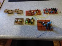
Here are some modules from past stuff. The nice ones on PCB's are from a place called Morning Distributing Co. that specialized in little pre fab building blocks, but now long out of business. The top row is a single conversion SSB receiver, with audio AGC, less the oscillators and filters. Bottom row is second mixer / IF / FM Detector / squelch and audio. I have a bunch more bits like this, some would need to be harvested from a homemade general coverage AM receiver I haven't used in decades.
I might put some tuned circuits in the RF amp board and give it a try. I need to do some roofing today, so may not get to it this weekend.
Win W5JAG
Attachments
Did I already give a JFET rant? If so, here I go again.Yes, hobby grade all over the place parts. Sometimes called "floor sweepings". Obsolete in both leaded and SMD, but still in demand, so genuine ones are more expensive than good parts. I got a bag of 25 plastic leaded J310's from Dan's Small Parts for $10 USD or so - can't get real MPF102's for that. Dan's has some SMD MPF102's but I haven't tried any of those.
I think 2N3819 is another hobby grade part after everything better was picked out.
I've never designed or used JFETS in a circuit, though I read about them and known the theory of operation as long ago as the late 1970s.
But there's the new (to the USA) Amateur Radio bands in the LF and VLF ranges that I want to build something for, so I've spent the last year or so looking up and learning about different JFETS (for a high impedance front end for an LF/VLF band receiver), and there are so many part #'s all over the web, even for audio preamps or electric guitar high-impedance buffers. Google any of these with the added word FET or JFET and you'll get plenty of schematics with JFET part numbers, just about all of them obsolete! I've read elsewhere (like here Is the J113 FET a direct replacement for MPF102 FET? | QRZ Forums) about the MPF102 and why it's not made anymore, but so many other JFETS are also obsolete it's frustrating. Even some JFETs listed as "currently available" and suggested in "The Art of Electronics" Third Edition are no longer made! The book does have a nice, ahem, "FFT" diagram [FET Family Tree] that explains what types are made, and is easier to follow than the text description in the 2nd Edition.
I do have some J1xx and/or J2xx parts, some I've ordered recently, and I found a bag of 10 I ordered from Digikey ten years ago (!) and never used. I forget the exact part# offhand, but you guessed it, they don't make those anymore.
After what seems like a large amount of research, I think I've finally learned not to worry so much about it, as it seems many/most JFETS are interchangeable as long as you watch out for a range of pinchoff voltage and such.
- Home
- Member Areas
- The Lounge
- No RF gear here?