The best all-around 500v caps I have are the Black Gate WKZ series, but unfortunately they are no longer made. I have tried several other types since then and the best ones are the Mundorf M-TubeCap (actually a film cap) and the Jensen.
The Mundorf sounds very good. Compared to the BG WKZ, the Mundorf is a bit warmer and less bright, and also does not have the recessed mids of the BG caps. However, the Mundorf doesn't have the overall speed and frequency extension of the BG. I do not like the Jensen as much as the Mundorf. The Jensen has fairly good detail and deep bass, but it is rather dark and heavy sounding. The Jensens I have tried are all 100 + 100 uf/500v. The Mundorfs I have used are all single 100uf/550v.
The Mundorf sounds very good. Compared to the BG WKZ, the Mundorf is a bit warmer and less bright, and also does not have the recessed mids of the BG caps. However, the Mundorf doesn't have the overall speed and frequency extension of the BG. I do not like the Jensen as much as the Mundorf. The Jensen has fairly good detail and deep bass, but it is rather dark and heavy sounding. The Jensens I have tried are all 100 + 100 uf/500v. The Mundorfs I have used are all single 100uf/550v.
My point of view is that any design that is serious about sound quality wouldn't have an electrolyte in the signal path anyway, so the question is moot. Bias can be had with LEDs for example and PSU's should be isolated behind a regulator. Does wonders to the sound quality in my opinion.
My point of view is that any design that is serious about sound quality wouldn't have an electrolyte in the signal path anyway, so the question is moot. Bias can be had with LEDs for example and PSU's should be isolated behind a regulator. Does wonders to the sound quality in my opinion.
There was no mention of 500V electrolytics in the signal path in the OPs question, so the question is in no way moot. I was thinking the question was in reference to the power supply.
Last edited:
The good quality ones that don't pop and thus keep the amp working")
I agree
My point of view is that any design that is serious about sound quality wouldn't have an electrolyte in the signal path anyway, so the question is moot. Bias can be had with LEDs for example and PSU's should be isolated behind a regulator. Does wonders to the sound quality in my opinion.
Fact of life: electrolytics (in the hundreds) are used in the sound path of every studio console whether one likes it or not: economics.
The 500V elco types I come across, typ Farnell stock 536490,536519,1369534 all screw types and not cheap, often have horrendous delivery times.
The only way I get out of the problem is to double up in series with mass produced 105°C types, space takers which is annoying. I often use 600V B+ where a series cap combination is a painful unavoidable solution.
richy
Attachments
<Snip>
I get out of the problem is to double up in series with mass produced 105°C types, space takers which is annoying. I often use 600V B+ where a series cap combination is a painful unavoidable solution.
richy
richy,
Please share with us! When you use capacitors in series to raise the working voltage do you also place series resistors in parallel and tie the nodes together to keep the center point voltage at half the B+. I read stories that without the resistors alongside the voltage at the point where the top capacitor’s minus terminal ties to the bottom capacitor’s positive terminal will drift from the B+/2 point.
What works for you?
DT
All just for fun!
richy,
I read stories that without the resistors alongside the voltage at the point where the top capacitor’s minus terminal ties to the bottom capacitor’s positive terminal will drift from the B+/2 point.
Hey there,
the resistors in parallel to the caps act as a voltage divider, giving the center point the defined value B+/2.
Leaving them out means that the (possibly changing in operation) series resistance of the caps determines the voltage divider. As especially electrolytics arew often quite different even within one production run, you can not count on exactly matched series resistances.
If they differ significantly, the cap with the higher series resistance sees the higher voltage, maybe too high ---> Boom!
So stacking caps for higher voltage capability should always include a resistive potential divider to set the center point voltage correctly.
Note for dimensioning the R's: Current through the resistors should be (significantly) higher than the leaking current of the caps.
Greetings,
Andreas
Rundmaus,Hey there,
the resistors in parallel to the caps act as a voltage divider, giving the center point the defined value B+/2.
Leaving them out means that the (possibly changing in operation) series resistance of the caps determines the voltage divider. As especially electrolytics arew often quite different even within one production run, you can not count on exactly matched series resistances.
If they differ significantly, the cap with the higher series resistance sees the higher voltage, maybe too high ---> Boom!
So stacking caps for higher voltage capability should always include a resistive potential divider to set the center point voltage correctly.
Note for dimensioning the R's: Current through the resistors should be (significantly) higher than the leaking current of the caps.
Greetings,
Andreas
That is the story as I know it. As Paul Harvey would say I want to know the rest of the story.
I want to hear the practical application. Stuff like capacitor matching, minimum current through the voltage divider and the story of probing the circuit voltages on the bench.
You know the vicarious DIY stuff.
DT
All just for fun!
I want to hear the practical application.
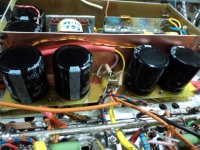
Picture of the practical application in one of my current projects:
http://www.diyaudio.com/forums/tube...aus-work-pp1c-without-sand-2.html#post2546319
The green ones are the parallel resistors, 150k 2W if I remember correctly, need to look it up in my paper stuff...
Stuff like capacitor matching
Unnecessary. Thats what the resistors are there for.
, minimum current through the voltage divider and the story of probing the circuit voltages on the bench.
Minimum divider current is a more complicated question, depending on the cap's DC leakage. I did not bother about that in the example above, for the following reasons: The resistors in my circuit are also used as bleeder resistors, draining the filter caps empty when switching the amp of - avoids nasty experiences when working inside the amp. Besides that, I calculated them quite low as to ensure a minimum load current on the PS and keeping the idle voltage from rising unacceptably high.
Both demands, bleeder function and some 'basic' load for the PS, lead to a quite high voltage divider current in the mA range - much higher than DC leakage of any practically available electrolytic cap.
Greetings,
Andreas
richy,
Please share with us! When you use capacitors in series to raise the working voltage do you also place series resistors in parallel and tie the nodes together to keep the center point voltage at half the B+. I read stories that without the resistors alongside the voltage at the point where the top capacitor’s minus terminal ties to the bottom capacitor’s positive terminal will drift from the B+/2 point.
What works for you?
DT
All just for fun!
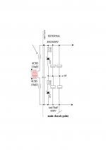
DT: okay this is the sch I generally use. Ignore the choke and other bits.
The two zener diodes in each half leg with divider resistors are there to avoid a complete cap discharge and keep cap etch polarised longer. Considering power electroytic caps are widespread, their cost keeps accelerating and any method of improving life and low operating temp is recommended.
richy
Attachments
1) The ultimate solution with polypropylene (when costs doesn't matter) you will find by page 19 about
http://www.icar.it/NewIcar/pdf/LNK_2011_Rev_01.pdf
2) By lower costs also very good results you will get with follow caps (scroll down):
http://www.ftcap.de/downloads/elektrolyt/datenblaetter_2010/GM2010.pdf
http://www.icar.it/NewIcar/pdf/LNK_2011_Rev_01.pdf
2) By lower costs also very good results you will get with follow caps (scroll down):
http://www.ftcap.de/downloads/elektrolyt/datenblaetter_2010/GM2010.pdf
This means a combination of number 1 and 2.If you use electrolytic's and space allows, bypass each one with a pair of ASC film/oils in series.
The ASC's have a reputation of very good SQ.
Last edited:
Lots of cool applications Guys, thanks for the vicarious fun!
This series capacitor stuff has the brain running, thinking about voltage doublers and bipolar power supplies with the center node grounded. There would be equal and opposite noise canceling ripple.
The last couple of trips to the local surplus store I bought a case of 200V 560uF capacitors and a dozen Triad 35 VA 120V input 120V output isolation transformers.
I will put on my safety glasses and see what happens.
DT
All just for fun!
- Status
- This old topic is closed. If you want to reopen this topic, contact a moderator using the "Report Post" button.
- Home
- Member Areas
- The Lounge
- Best sounding 500v. electrolytics