Thanks for the info. I'll start with the $25 signal generator as we have been using a discrete piece in my test kit.
Now can you tell me how to measure jitter to better than 200 ps for less than $10,000!
OK-
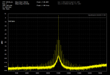
QA400 ($200) Jtest signal (found on the web, generator posted on DIYaudio somewhere, free)
The Minidac is pretty bad, but it was on the bench. What is clear is that getting a measurement with a jitter floor low enough to see anything relevant does not need to cost a lot.
Attachments
OK-
QA400 ($200) Jtest signal (found on the web, generator posted on DIYaudio somewhere, free)
The Minidac is pretty bad, but it was on the bench. What is clear is that getting a measurement with a jitter floor low enough to see anything relevant does not need to cost a lot.
Close, but I have a 48K clock that I want to measure the "Phase Noise" or jitter. But since the QA400 looks like a really spiffy toy I'll get one. I need to have at least 1/2 as much test equipment as you Dick, if I want to keep up!
I am eBay following a scope.
But do try to convince me to shell out for a Stanford analyzer with jitter capability. The AP current version I was quoted at $27K and to be honest watching the AP system 2 drop in value so fast has me put off on the line.
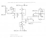
Check the schematics thoroughly, this buffer has almost no DC output offset .... like 150 microvolts or so. Depends on JFET matching.
Thanks for the sim results Pavel. I guess I'd have to build and test one for real but I just know its going to be opamps I use.
Mooly, I am not trying give you a specific design for YOUR needs, this schematic is over 20 years old and is intended for another company. It works fairly well down to 2K ohms or so, but 10K ohms and above is preferred.
It is just an ALTERNATE APPROACH to using an OP AMP for a buffer. It replaced the AD712 in one design with great success. It is not an 'idiot proof' design like an op amp is. It does have limited current drive, will NOT drive headphones, can be biased wrong and have lots of 2'nd harmonic, much more than one would want. Only high current versions of the 2SK170 or the 2SK389, etc will work optimally.
I realise that John, and I can see your whole design ethos is totally different to mine, but as I say to Pavel, it has to be opamp based really (for me).
Sensitive to shaking and mechanical impacts.
Back in the Piher horror days, a veritable artisan could be recognised by traces of paint, and a seal ring on the pinky finger.

Last edited:
How well I know those little black pots. Although, in their defense, they were significantly more reliable than the Piher dual pots with shafts.Back in the Piher horror days, a veritable artisan could be recognised by traces of paint, and a seal ring on the pinky finger.
Mooly, IF I had an 'ideal' op amp recommendation for your need, I would gladly give it to you. What amused me was that people who are always telling me that op amps are the way to go, gave you almost random advice as to which op amp to use. They don't (in general) know as much about op amps as I do, but they are quick to give advice.
General comment on this buffer side-topic. The dual JFET approach is of course tried and true, with some appreciable input capacitance change with input signal (one distortion mechanism that is sensitive to source impedance), and some appreciable sensitivity to loading. However with good duals at least, the output offset voltage will be small.
There are ways with more parts to alleviate both sources of error. A bootstrapped cascode on both upper and lower FETs will remove the drain-gate C variation almost completely, although will entail high frequency instability depending on the source impedance as there will be a negative input capacitance at high frequencies.
For dealing with the loading effects, for a fixed load impedance one can provide an auxiliary complementary negative impedance using a negative immitance converter fashioned from an opamp. Or, the lower device(s) can provide an injection point for a compensating current based on the buffer output voltage and load. The JFETs etc. will still be the dominant buffer, effectively, unless one is trying to drive fiercely low impedances.
If the loading is variable as discussed, from a potentiometer, a second potentiometer section ganged with the main load pot can provide a variable negative impedance when used with the negative immitance circuit.
I used an LSK170 as the input device on one power amp design where I wanted high input Z (LSK because of availability in SOT-23). Rather than provide a matched current generator in its source I used cascode bipolars and an overall d.c. servo. The negative impedance was resistive and one of the sections of a LME49720 was used for the negative immitance converter. I also needed some gain so the overall circuit is more complicated than a unity-gain buffer. The overall front end was also quasi-differential, and a future project is to precisely derive the equations for the resistor values, which were determined by tweaking simulations. But overall the circuit performed beautifully, and allowed the power amp section to dominate the distortion and most of the noise. Alas, four of us jumped off the ship due to conflicts with the company founder.
Mooly, IF I had an 'ideal' op amp recommendation for your need, I would gladly give it to you. What amused me was that people who are always telling me that op amps are the way to go, gave you almost random advice as to which op amp to use. They don't (in general) know as much about op amps as I do, but they are quick to give advice.
Well this is one project where I'm actually beginning to contemplate using different devices for the different stages based on (what I deem for each) the most suitable attributes.
Thanks again John. Hopefully in the weeks to come I'll be able to tell you all what I finally settle on.
because i have these on hand : E421 dual , 2N4393 . Are the resistive values correct ? Offset is correct but working temp is very high !Coresta, why did you use another type fet?

Close, but I have a 48K clock that I want to measure the "Phase Noise" or jitter. But since the QA400 looks like a really spiffy toy I'll get one. I need to have at least 1/2 as much test equipment as you Dick, if I want to keep up!
I am eBay following a scope.
But do try to convince me to shell out for a Stanford analyzer with jitter capability. The AP current version I was quoted at $27K and to be honest watching the AP system 2 drop in value so fast has me put off on the line.
hah! Only if you get the SRS .... which I am drooling for myself.
But the qa400 does a lot for a little and is enough for most test needs.
-'Dick'
because i have these on hand : E421 dual , 2N4393 . Are the resistive values correct ? Offset is correct but working temp is very high !
Pinchoff voltages are too high for your FETs. The 2SK389 parts, or matched 2SK170 pairs, are much lower pinchoff, and hence the resistor values John shows are appropriate.
Unfortunately, padding out the gate-source voltages with bigger resistors will result in a higher output resistance for the buffer.
hah! Only if you get the SRS .... which I am drooling for myself.
But the qa400 does a lot for a little and is enough for most test needs.
-'Dick'
I'd lend it to you, if you ever really want to play!
Close, but I have a 48K clock that I want to measure the "Phase Noise" or jitter. But since the QA400 looks like a really spiffy toy I'll get one. I need to have at least 1/2 as much test equipment as you Dick, if I want to keep up!
I am eBay following a scope.
But do try to convince me to shell out for a Stanford analyzer with jitter capability. The AP current version I was quoted at $27K and to be honest watching the AP system 2 drop in value so fast has me put off on the line.
it occurred to me that you would be measuring a 48K or 44.1K word clock. I can do that with a QA400 (or any FFT that covers that frequency). I think I can pull the work clock out of my RME card and see what we see.
The problem with measuring jitter with a time interval analyzer (SR420 or HP5370) is that they look at cycle to cycle. If you add 20 pS to each cycle in a cyclic fashion is doesn't show in the instrument and is really obvious when you look at it differently. I confirmed this modulating an FM signal into the HP5370. It has a 20 pS single cycle resolution and 24 MHz FM modulated hard did not show. Wrong way to look at it.
Either a modulation analyzer, a real phase noise analyzer or a tweaked FM tuner are the solutions for looking at Jitter on the clocks.
Either a modulation analyzer, a real phase noise analyzer or a tweaked FM tuner are the solutions for looking at Jitter on the clocks.
I wonder whatever happened to Ed Meitner's jitter analyzer box that Stereophile used to use?
General comment on this buffer side-topic. The dual JFET approach is of course tried and true, with some appreciable input capacitance change with input signal (one distortion mechanism that is sensitive to source impedance), and some appreciable sensitivity to loading. However with good duals at least, the output offset voltage will be small.
There are ways with more parts to alleviate both sources of error. A bootstrapped cascode on both upper and lower FETs will remove the drain-gate C variation almost completely, although will entail high frequency instability depending on the source impedance as there will be a negative input capacitance at high frequencies.
For dealing with the loading effects, for a fixed load impedance one can provide an auxiliary complementary negative impedance using a negative immitance converter fashioned from an opamp. Or, the lower device(s) can provide an injection point for a compensating current based on the buffer output voltage and load. The JFETs etc. will still be the dominant buffer, effectively, unless one is trying to drive fiercely low impedances.
If the loading is variable as discussed, from a potentiometer, a second potentiometer section ganged with the main load pot can provide a variable negative impedance when used with the negative immitance circuit.
I used an LSK170 as the input device on one power amp design where I wanted high input Z (LSK because of availability in SOT-23). Rather than provide a matched current generator in its source I used cascode bipolars and an overall d.c. servo. The negative impedance was resistive and one of the sections of a LME49720 was used for the negative immitance converter. I also needed some gain so the overall circuit is more complicated than a unity-gain buffer. The overall front end was also quasi-differential, and a future project is to precisely derive the equations for the resistor values, which were determined by tweaking simulations. But overall the circuit performed beautifully, and allowed the power amp section to dominate the distortion and most of the noise. Alas, four of us jumped off the ship due to conflicts with the company founder.
The proverbial schematic that may be worth a few kilowords attached. The opamp is an ideal flat gain of 10^5, but the 49710 etc. work very well. The distortion at 1kHz and 5V peak out to the 19th harmonic is predicted to be about 16ppb, mostly second and third. And that's still mostly due to input distortion for the source resistance of 1kohm, due to the residual voltage-dependent input capacitance. Due to the negative-immitance-generator load compensation, the distortion due to variation in active device currents is very small. The feedback resistors in the NIG can be made smaller for a larger signal range at a small noise penalty.
Bandwidth is -3dB at about 17MHz, with minimal peaking.
Attachments
Well, that died a quick death; only SY showed interest. Considering what this game is supposedly all about, getting transparent replay of recorded material, it's curious how there's no real concern for such "bigger",
issues ...Maybe the fun of playing with all the bits under the hood of the old car is the name of the game ...
Frank
Last edited:
Well, that died a quick death; only SY showed interest. Considering what this game is supposedly all about, getting transparent replay of recorded material, it's curious how there's no real concern for such "bigger",
Maybe the fun of playing with all the bits under the hood of the old car is the name of the game ...
Frank
We've tried, when put up or shut up happens one side backs off. As I said, too much to lose. It's that no peaking by any means thing, kills it every time.
BTW OT, I saw a bumper sticker yesterday "I want Morgan Freeman to narrate my life" LMAO.
Last edited:
- Status
- Not open for further replies.
- Home
- Member Areas
- The Lounge
- John Curl's Blowtorch preamplifier part II