Now John's going to shout at you for passing signal current through the pot wiper.
Probably
Four?! Care to share a circuit?
Its based on Doug Selfs precision preamp with continuously variable turnover points for bass and treble.
Simon, you might look here not sure on the exact $ damage, but pretty sure its going to be under $10K. he uses a LeCroy real time Digital Scope plus JTA measurement package, his noise floor is ~2ps and describes his measurement setup, pretty special results too.
Demian can probably make some good recommendations too
Demian can probably make some good recommendations too
Last edited:
For my intended use ...... Also DC offset has to be low, because there are no caps coupling the four pots used.
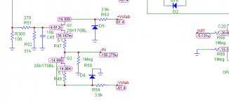
Check the schematics thoroughly, this buffer has almost no DC output offset .... like 150 microvolts or so. Depends on JFET matching.
Attachments
Last edited:
Mooly, I am not trying give you a specific design for YOUR needs, this schematic is over 20 years old and is intended for another company. It works fairly well down to 2K ohms or so, but 10K ohms and above is preferred.
It is just an ALTERNATE APPROACH to using an OP AMP for a buffer. It replaced the AD712 in one design with great success. It is not an 'idiot proof' design like an op amp is. It does have limited current drive, will NOT drive headphones, can be biased wrong and have lots of 2'nd harmonic, much more than one would want. Only high current versions of the 2SK170 or the 2SK389, etc will work optimally.
It is just an ALTERNATE APPROACH to using an OP AMP for a buffer. It replaced the AD712 in one design with great success. It is not an 'idiot proof' design like an op amp is. It does have limited current drive, will NOT drive headphones, can be biased wrong and have lots of 2'nd harmonic, much more than one would want. Only high current versions of the 2SK170 or the 2SK389, etc will work optimally.
Last edited:
yeah because good opamps are so easy to apply correctly, even an idiot child could do it. now lets see your high quality modern wide bandwidth opamp PCB layouts John...
I quite like discrete circuits as you can bend them to do things ICs cannot always do, or to suit a specific application, and because its fun to build, but i'm under no illusions that a high quality high performance build using opamps; that meets the often ludicrous datasheet specifications is a piece of cake. in many ways it can be more difficult.
i'm agnostic in this regard, I use what I feel like and what I feel suits my application. I dont care if its discrete or opamps
Last edited:
Check the schematics thoroughly, this buffer has almost no DC output offset .... like 150 microvolts or so. Depends on JFET matching.
Pavel I guess this is with perfect matched devices, perfect matched supply zeners...?
jan
I quite like discrete circuits as you can bend them to do things ICs cannot always do, or to suit a specific application
I'd be interested in some examples here.
jan
Pavel I guess this is with perfect matched devices, perfect matched supply zeners...?
jan
First, it is the simulation. But, the real thing has very low DC output offset as well, if JFETs are well matched. Zeners are not that critical. The circuit published does not show decoupling.
BTW, nice part in your avatar. John might consider to use it in his new product line
I'd be interested in some examples here.
jan
high voltage, high power, access to bias or other 'internal' local FB loops/degen that may tweak operating point for the specific load that may not be brought out on the opamp pins. some of these things can be achieved with a mixed IC/discrete layout as well, but as a self confessed opamp lover, there are some things that you are more free to do with discrete.
you dont really feel that an opamp is always the best choice do you?
also i'm not so much talking of the limitations of the technology, moreso the limitations of available devices. an IC could be designed to do just about anything, some of the internal parts/features are difficult to match whats possible with external larger parts like very linear higher capacitance are just too large for the most part to have internally. the flexibility of discrete is hard to beat, though given access to the technology and budget it would be very cool to be able to generate custom application specific ICs. one day i'm sure, probably sooner than we think.
Last edited:
On the Virtins Technology software package mentioned earlier they are also showing the separate external oscilloscope modules to the right of the page. Is this only a capture card application or is there something I am missing here with those? How do those interface with the software and what do they add to the picture? Humor me as I am trying to understand all of what is being said here...
But, the real thing
A surface mount 10-20R trimpot is smaller than a TO-92 footprint.

PMA (or anyone that cares to answer), do you have any idea what an average amount of parasitic capacitance and inductance might be for a trimpot say 5k at HF? less than 10-20pf? we are looking to replace a trimpot for bias with some parallel SMD 0603 fixed resistors and a pair of opto isolated relays (remotely controlled with an MCU, the specific part is IXYS CPC1117N), which are LED and fet based. the Vbias is generated across a 2ma CCS on the LME49830 bias circuit.
I started worrying about unwittingly adding some less than linear lumped ciss/coss from the fets that interferes with the compensation. these elements, as well as the fet bandwidth could interfere with loop stability/phase angle.
that being said its replacing a pot, which I know has some parasitic C and L already, but its not something specified in datasheets.
the idea is to allow some optimal/smart/automated and remote bias setting wrt ambient temp/month of the year, as well as allowing the chip and power supply to start up into a lowish 100ma bias, then after a few seconds increase to 400 or 600ma for more class A and lower distortion, based on set environmental variables.
Last edited:
For the record, I don't layout my own designs. My associate has been doing the layouts for the last 30 years, and he is a pro in the layout business. High frequency does not bother him. I consider his efforts close to my own in value, and ALL the Parasound JC series, as well as the Vendetta Research, CTC Blowtorch, and many other products were all done by him at my insistence. He is the T in CTC.
- Status
- Not open for further replies.
- Home
- Member Areas
- The Lounge
- John Curl's Blowtorch preamplifier part II