George
All I did was laugh and wait to see how many nasty responses followed. Instead there was your nice polite explanation. So I won't quibble with it.
But I think you should realize that polite explanations are not in keeping with this thread.
ES
I woke up in a good mood today and I promised to be a good boy all day long (7 hours remain
 ).
).George
This is not a little excessive?I promised to be a good boy all day long
George
All I did was laugh and wait to see how many nasty responses followed. Instead there was your nice polite explanation. So I won't quibble with it.
But I think you should realize that polite explanations are not in keeping with this thread.
ES
My reply was the polite version...
George
All I did was laugh and wait to see how many nasty responses followed. Instead there was your nice polite explanation. So I won't quibble with it.
But I think you should realize that polite explanations are not in keeping with this thread.
ES
That patent was fun, notice how the room temperature was not recorded even though a store bought thermometer was used for .1 degree resolution on the mineral oil.
To be fair precision calorimetry is very hard to do.
Kindness pays back (so they say).This is not a little excessive?
Ed see upper part from page 5 of attachment.
For magnetostriction and distortion for some core materials, see this link http://www.sowter.co.uk/pdf/GAVS.pdf
George
Attachments
My reply was the polite version...
You just mentioned the correct methods, George explained why.
George,
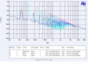
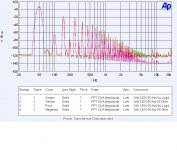
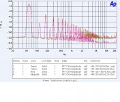
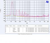
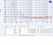
Attached are the distortion curves from an R-core transformer, a Toroid and a standard E-I. These were obtained from a clean sinewave source.
The R-core is used on a 220 Volt primary and shows almost no power line distortion. This is obviously because the core did not saturate at all.
The Toroid is almost as clean.
The E-I core shows a lot more distortion when measured at 60 hz and even more distortion as the frequency is dropped to 50 hz. That seems to be from saturation. At full load with 10% high voltage at 50 hz the core noticably heats up and that is what seems to limit the power rating. Flux leakage is also at a maximum for a clean load.
I also have included E-I cores used center tapped with a pair of diodes providing power into a 50 ohm load filtered by a 2200 uF capacitor. Now how much of that noise comes from the core distortion, the rectification process or the incoming AC line?
ES
Attachments
George,
ES
Ed thank you for the FFTs
First I would like you to confirm that these FFTs are from voltage measurements on the secondary side.
I would think as follows (remember, it is you who asked for itI also have included E-I cores used center tapped with a pair of diodes providing power into a 50 ohm load filtered by a 2200 uF capacitor. Now how much of that noise comes from the core distortion, the rectification process or the incoming AC line?
)Pick one trafo.
Step 1. Make one measurement of the unloaded transformer when fed from the mains.
Step 2. Make a second measurement of the unloaded transformer when fed from the amplifier (same freq, same voltage with the mains).
Step 3. Make a third measurement of the loaded transformer when fed from the mains.
Step 4. Make a forth measurement of the unloaded transformer when fed from the amplifier (same freq, same voltage with the mains).
Provided that amplifier has a very low impedance:
Step 5. Comparing (subtracting) the FFT of Step 2 and Step 1 will give you the influence of the incoming AC line with trafo in unloaded state.
Step 6. Comparing (subtracting) the FFT of Step 3 and Step 1
The FFT of this subtraction will show higher components of AC even harmonics. This is bound to happen.
Check for difference in odd harmonics and any other new products. These should be called the “noise from rectification” for the psu fed from the mains.
Step 7. Now, do the same comparing (subtracting) the FFTs of Step 4 and Step 2
You will get the “noise from rectification” for the psu fed from the amplifier.
Step 8. Compare (subtract) the FFTs of Step 6 and Step 7.
Study the “noise from rectification” on these two FFTs.
Most probably the FFT of Step 7 will be cleaner from FFT of Step 6
This will be due to finite impedance of main’s incoming AC line plus line noise.
Step 9 (optional ) Compare (subtract) the FFT of Step 8 and Step 3.
This should confirm the influence of main’s line impedance on rectification process on the secondary side of the trafo.
Step 10 (mandatory) Switch off bench power and enjoy a glass of whatever you like, anywhere you like, with whomever you like.

George
By George I think you've got it! I think you've got it again!
Actually it is easier than that!
Yes I am looking at the secondary voltage and 0 db is 1 volt RMS.
I am cleaning up the same curves from the AC line to show the additional line noise for the 60 hz comparisons, but at only one voltage.
The toroid (and R-core but as it has a different secondary voltage might mislead some.) has low enough distortion that I can feed it from clean AC and show the effects of rectification. I can also run all of the others to show the variance.
So that will show, the distortion of the transformers, the AC line noise and the rectification noise.
Now the interesting issue is that some off the distortion from the transformers is on the same frequency as the rectification noise but out of phase!
Now the interesting issue is that some off the distortion from the transformers is on the same frequency as the rectification noise but out of phase!
Ed
Check which harmonics are these.
Odd harmonics (3rd to 11th) on mains change with time not only in amplitude but in phase as well. This is due to unequal loading of the phases on utility local distribution.
George
PS. I don’t see the glass on your hand.
Ed
Check which harmonics are these.
Odd harmonics (3rd to 11th) on mains change with time not only in amplitude but in phase as well. This is due to unequal loading of the phases on utility local distribution.
George
PS. I don’t see the glass on your hand.
I was looking at the results from the clean AC source.
It is still a bit early here.
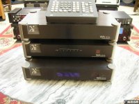
Stupid question 1 : How many (serial) preamp models, with cases out of a solid chunk of easy to machine aluminum, were there at the time of BT No2 ('97)?
Stupid question 2 : How many now (+ power amps/phono stages/DAC's) ?
(aviation/military not acceptable)
No idea jacco
I was looking at the results from the clean AC source.
It is still a bit early here.
here are some harmonics on an otherwise clean ac line... only a lamp dimmer on the light (turned on).
-RNM

RNM,
Why is that meter optimized for 50hz electrical service? Why not 60hz and is that something that matters or does it just extend the range of the meter? That is a 43B meter right? Just wondering what difference that makes to the test results.
The meter says 59.97Hz. Might as well be 60Hz.
se
Steve E,
I was looking at the Fluke website and it listed the meter as a 50hz meter and that is why I asked that question. I guess you are saying that it is something you can chose for the test point. Perhaps it is auto-setting and picks up the power line frequency? For some reason my internet connection is so poor that many times I don't get the complete image when I try to zoom in on the image on the page so it is hard to see some of the details on the scope screen.
I was looking at the Fluke website and it listed the meter as a 50hz meter and that is why I asked that question. I guess you are saying that it is something you can chose for the test point. Perhaps it is auto-setting and picks up the power line frequency? For some reason my internet connection is so poor that many times I don't get the complete image when I try to zoom in on the image on the page so it is hard to see some of the details on the scope screen.
John's Blowtorch wasn't the only product with machined aluminium enclosure on the market, by the way. Wadia did the same with their "flagship" DAC.
Anyone want to give Wadia a call and offer them assistance in enclosure design? I'd love to hear Wadia's response
Anyone want to give Wadia a call and offer them assistance in enclosure design? I'd love to hear Wadia's response
Attachments
- Status
- Not open for further replies.
- Home
- Member Areas
- The Lounge
- John Curl's Blowtorch preamplifier part II