I'd probably try a 5534 first, partially because of the flexibility of the external compensation. Iq is 4mA typ., 8mA max., and that 8mA is probably a sort-of CYA n-sigma outlier number.
From the schematic I saw it looks like there will be at least ~300uA flowing all the time, so your output devices will stay on all the time to some extent.
Of course, insist on genuine parts! I can only imagine what sort of counterfeits there may be out and about.
From the schematic I saw it looks like there will be at least ~300uA flowing all the time, so your output devices will stay on all the time to some extent.
Of course, insist on genuine parts! I can only imagine what sort of counterfeits there may be out and about.
for an op amp with a "hot" output stage, why not the old AD811?
or the less old AD815?
mlloyd1
Blindingly-fast current-feedback amps tend to oscillate without much provocation, and I suspect the AD811 is no exception. If the output devices (as yet unspecified) contribute both significant gain and phase shift, I think things are likely to scream. And the quiescent current is 16.5mA, which with beta-of-even-50 output devices is a whole bunch of collector current. But why not try it?
for an op amp with a "hot" output stage, why not the old AD811?
or the less old AD815?
mlloyd1
The AD815 does well without external help on headphones. I documented well the thermal response at low frequencies (DC) just for you guys since the xDSL folks don't care.
My preferred way of making a "low impedance load driver for Op-Amp's" has a similarly low parts cound and is also targeted for 100...200mA Iq...
A total of 3 parts (2SC5171 or 2SA1930 depending if we want to pull the Op-Amp output up or down to put it into SECA, LM317 and one resistor) and we are SE Class A, including the Op-Amp output.
That's about 1 ma (order of magnitude) base current in the output transistor. Is that enough to turn off one of the opamps transistors reliably?
Now a question of definition - how would this sort of output stage be classed (SE-A, PP-A, AB etc) if one transistor were on for the entire cycle, while the other was off at idle (due to DC current drawn from the stage) but turned on for part of the cycle due to the AC current draw?
For the record, the humble uA741 works pretty good in this amplifier. Amazing isn't it? Why?
Because the output transistors are connected in common emitter mode ,
thus providing effective voltage gain , hence , if they have let s say
a 20dB voltage gain , the poor 0.5V/uS slew rate of the 741 will be increased
accordingly , as well as GBW product , of course.
Last edited:
John, why are you proposing a common emitter output and not common collector for this design?
I'd think with rails at +- 15 you'd have no output swing issues. 3V peak into almost any headphone you care to name would blow your ears out anyway.
Surely the best option price/complexity/perfs wise.
A 5534 + 2 output power devices should allow to push down
10Khz THD contents below -100dB at 4V rms/30R , the targeted output level,
while retaining the 100mA Iq.
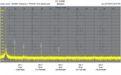
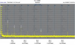
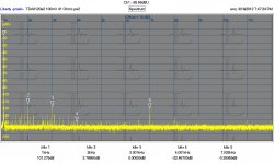
What about this: http://www.ti.com/lit/ds/symlink/tpa6120a2.pdf 100 MHz and .0002% THD? The 7th harmonic isn't much less than the 2nd, but they are both in the -110 dB range with no load. Almost no external parts. The plots below I just measured.
For what its worth except on the most insensitive headphones (Audeze? which is what I used as a load) even 100 mV is ear splitting loud. With a load the distortion increases but still really low.
This may not be the last word in headphone amps but you can't ignore it now. At least you get a lot for $2.00.
I have also found that a series resistor never seems to help. A voltage drive always seems to sound better, unless the bass depends on major resonance, which will usually sound pretty woolly in a headphone.
Attachments
interesting choice John, you point out that the input op amp in your circuit doesn't require high slew rate, nor high output current
then you select an op amp which has both - and at a high price in performance specs that might matter
the AD825 12 nV/rtHz noise is speced at 10 kHz - datasheet writers only do that when the 1/f corner is over 1 kHz - and 12 nV is poor, expecting several times that at 1 kHz is worse for audio
noise is consequential in headphone amplifiers with higher sensitivity headphones
I use a 10 kOhm volume pot just to keep Johnson noise low, wouldn't use an op amp that gives noise figure even 3 dB worse
Samuel Groner's Op Amp Distortion measurement paper ends his AD825 section with
http://www.sg-acoustics.ch/analogue_audio/ic_opamps/index.html
lots lower noise fet input op amps exist, not every product can afford the OPA627 but even at the AD825 price level there are options
look at the OPA1641 - 5.1 nV/rtHz, 20 V/us, 11 MHz GBW
normally I wouldn't consider 1 nV/rtHz class low noise bjt input op amps in this position but even they can still beat the 825 on worst case noise with their ~2 pA/rt/Hz current noise and 20 kOhm or less volume pot - OPA1611
there are even CMOS op amps that beat on noise vs AD825 and cost less than $1
Demian, I have been proposing a composite circuit with "good, "audio" input op amp wrapping a outer feedback loop around the TPA6120 - doesn't seem to float John's boat - even mentioning that his buddy Walt Jung likes the topology for audio doesn't seem to help
then you select an op amp which has both - and at a high price in performance specs that might matter
the AD825 12 nV/rtHz noise is speced at 10 kHz - datasheet writers only do that when the 1/f corner is over 1 kHz - and 12 nV is poor, expecting several times that at 1 kHz is worse for audio
noise is consequential in headphone amplifiers with higher sensitivity headphones
I use a 10 kOhm volume pot just to keep Johnson noise low, wouldn't use an op amp that gives noise figure even 3 dB worse
Samuel Groner's Op Amp Distortion measurement paper ends his AD825 section with
...Not particularly well suited to low distortion applications, and relatively expensive
http://www.sg-acoustics.ch/analogue_audio/ic_opamps/index.html
lots lower noise fet input op amps exist, not every product can afford the OPA627 but even at the AD825 price level there are options
look at the OPA1641 - 5.1 nV/rtHz, 20 V/us, 11 MHz GBW
normally I wouldn't consider 1 nV/rtHz class low noise bjt input op amps in this position but even they can still beat the 825 on worst case noise with their ~2 pA/rt/Hz current noise and 20 kOhm or less volume pot - OPA1611
there are even CMOS op amps that beat on noise vs AD825 and cost less than $1
Demian, I have been proposing a composite circuit with "good, "audio" input op amp wrapping a outer feedback loop around the TPA6120 - doesn't seem to float John's boat - even mentioning that his buddy Walt Jung likes the topology for audio doesn't seem to help
Last edited:
Actually, the alternative suggested by JCX, has just as much peak output. It just does not have as much CLASS A output . . . very high rev'ing one.
I know that. That's why I cannot understand why you're going for a common emitter output stage.
Use a decent opamp (5532/34 or a 49710 for example) and wrap it around a simple class A push pull follower and you have single digit ppm at 20KHz up to 3V out and no nasty poles to have to worry about in the output stage.
The TI TPSxxxx device is also very good, but I can understand the reluctance for an all IC solution when there are more difficult ways to achieve the objective (joke!)
[snip]
I have also found that a series resistor never seems to help. A voltage drive always seems to sound better, unless the bass depends on major resonance, which will usually sound pretty woolly in a headphone.
I'd conjecture that the series resistor is an artifact of the earliest headphone outputs on the front panel of "integrated" amps/receivers, where the speaker connections were routed through closed-circuit jacks and the simple goal was to limit the power to the phones when plugged in. Bad news all around --- the contacts go south and interfere with the speaker drive, the cans are driven from a high impedance and, unless the makers have carefully taken this highish drive impedance into account, suffer from frequency response anomalies and nonlinear distortions.
- Status
- Not open for further replies.
- Home
- Member Areas
- The Lounge
- John Curl's Blowtorch preamplifier part II