Of course, tough where I live now, in the country side, RFI carried by mains supply may be much worse than RF radiation inside my house.
Is there any way around it? Is there any better solution?
There are some things that help:
- smallest possible loop area of each circuit stage, to reduce the electromagnetic 'moment' (leverage)
- 'stopper' resistors VERY close to transistor or valve input pins;
- simpler circuits arranged to avoid accidental demodulation;
- circuit architecture with input AND output referred to GND e.g. folded (shunt) cascode - has much higher immunity to EM-coupled noise - together with Circuit surrounded with copper ground.
I find that circuits built like this have excellent rejection of coupled noise, all the way from transformer fields to DECT & mobile telephone handsets held right up to the circuit.
Been finishing a system, but I have to put my $.02 in.
Shunt regulators have advantages over series regulators in particular when driving swinging inductor loads. Sometimes the load can source current rather than just sink it.
I prefer a resistor fed from a voltage regulator rather than a current source to feed a shunt. Both the series regulator and the current source at high frequencies pass more noise due to what may be modeled as "capacitance." With a resistor driving the shunt element, the "capacitance" of the shunt now loads the resistor and provides passive attenuation assuming the active feedback is approaching unity or less. There also are issues of two active devices in series with slight or even not so slight nonlinear behavior interacting.
It is nice to use circuit theory to model much of what we do, but when you are hitting the limits, expect nonsense.
I do find it interesting how much attention has been paid to shunt regulators since June 2007th. Which must be their re-birth date. (Note this is an ego exercise.)
High frequency noise can be addressed by treating the equipment enclosure as a Faraday cage. Small openings, no straight line from the openings to internal wiring, bypassing almost everything to the case and understanding that at high frequencies electromagnetic fields like to "stay tight". (Sorry I will not elaborate on that, there is good material elsewhere and if I remember where I will post the links.)
I also like to use simple fixed voltage at the base of a transistor and the output from the emitter for a regulator. This can be modeled as a gyrator and has all sorts of complex behavior. Properly tuned this may provide "musical" benefits.
One of the secrets to audio power amplifier design is the "voicing" of the power supply. Having the right internal impedance for the VA output will affect low frequency sound, clipping effects and whole lots of other stuff. The idea of having a massive transformer feeding steriod grown capacitors is nice, but even those are limited by power line sags. Adding small RF (EMI to the hip) filters changes the power supply voicing. Please note that the stiffer the transformer the smaller the phase angle for capacitor charging and the greater the line sag effects.
Now for an aside, I just tried to install an AM transmitter in a new arena. The local AM station is 50KW at 15.7 miles from the venue and I have to use an external antenna and distribution system to get any reception inside the building! The idea was to rebroadcast the event coverage with a small transmitter inside the building.
Legal power limits are .1 watt and a small antenna. Using this, the range to my "classic 6 transistor" radio was less than 25 feet. Try number 2 was 212 feet of cable attached to a class D transmitter with a final input power of 30 watts. I had to use fan cooling as even the output inductors were getting really hot. Final range 90 feet!
It seems each light is on a dimmer, the LED display boards (Hundreds of them), the LCD TV's, the cell phone repeaters, the internal data networks (telephone, TV, sound, building control, security all are ethernet based) all emit legal limits of RF, but when combined are stronger than the local broadcasters!
Most folks understand the sine(x) + 1/3sine(3x) etc. At 120 hertz rate the 1/833sine ain't much by each contributor but the entire choir is really loud. Maybe you do not have as much at home, but it is the wave of the bluetooth mobile future!
ES
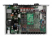
the aforementioned gear
A pic is worth 1K words, total of 10, including the 6 on the PS board.
(the slick 069 CD player has them as well, also 6 of the BNX on the PS board. Same setup in the 808-MK5, 070, etc.)
Attachments
One of the secrets to audio power amplifier design is the "voicing" of the power supply. Having the right internal impedance for the VA output will affect low frequency sound, clipping effects and whole lots of other stuff. The idea of having a massive transformer feeding steriod grown capacitors is nice, but even those are limited by power line sags. Adding small RF (EMI to the hip) filters changes the power supply voicing.
Indeed, unless the chokes on those small RF filters are made of really thick wires, about 1mm or more. As far as I can see, RF chokes made of really thick wires shouldn't impact the mains power sag. Unless there is something about such RF filters and chokes that I didn't account for.
And now...for something totally different...
This is a bit off the current topic, and I don't know if this is common knowledge here, but I had not seen it yet discussed. I recently came across this link to the Bell System Technical Journal archives 1922-1983:
Bell System Technical Journal
BSTJ is sort of a holy grail for some of us old audio/radio engineering farts. Much original research into just about everything having to do with audio is contained in these pages. I looked around for an index, but no luck. It has not stopped me from spending way too much time perusing the links. Oh - the speed and availability are pretty limited,
  but a couple of tries usually gets the DL.
Back to the discussion of interference, a subject near and dear to my heart as a radio engineer.
Howard Hoyt
CE - WXYC-FM 89.3
Chapel Hill, NC
1st on the Internet
This is a bit off the current topic, and I don't know if this is common knowledge here, but I had not seen it yet discussed. I recently came across this link to the Bell System Technical Journal archives 1922-1983:
Bell System Technical Journal
BSTJ is sort of a holy grail for some of us old audio/radio engineering farts. Much original research into just about everything having to do with audio is contained in these pages. I looked around for an index, but no luck.
It has not stopped me from spending way too much time perusing the links. Oh - the speed and availability are pretty limited, but a couple of tries usually gets the DL.Back to the discussion of interference, a subject near and dear to my heart as a radio engineer.
Howard Hoyt
CE - WXYC-FM 89.3
Chapel Hill, NC
1st on the Internet
any significant power sag on RF coils would probably burn them up quickly or not?
I would like to see a practical example where appropiate RF filters change clipping effects etc.
Regards
No, the duty cycle is very low and the average power stays the same. It is a simple test just about anyone can do it.
No, the duty cycle is very low and the average power stays the same. It is a simple test just about anyone can do it.
Ed were you talking about filters on the mains side or after the reservoir caps?
jan didden
Not to knock this study in emi noise reduction off track (I have opinions but this may be more interesting) here is a really novel amp measurement from the upcoming AES:
P7-5 New Techniques for Evaluating Audio Amplifiers via Measuring for Induced Wow and Flutter and Differential Phase Distortions—Ron Quan, Ron Quan Designs - Cupertino, CA, USA
Tough question would be; "Since all the information about the signal is also contained in the Fourier domain what could not be done with a sufficiently sampled signal and DSP ?"
At least there are no claims of in-harmonic signals.
Last edited:
Ed were you talking about filters on the mains side or after the reservoir caps?
jan didden
Filter on the mains.
Tough question would be; "Since all the information about the signal is also contained in the Fourier domain what could not be done with a sufficiently sampled signal and DSP ?"
Scott,
That raises the interesting question about the theoretical versus actual limits. Time for me being finite, noise one bane, not to mention the issue of modeling versus reality, are some of the limits, properly controlled probably not an issue. A good topic for intelligent discourse. One I have personally benefited from. So thanks from me for your knife edge of intellect.
But looking sideways at a problem may yield a shortcut.
But then the Holy Grail is a single figure of merit. Even my clothier's mirror has three facets.
But the pursuit of the Grail is a noble if foolish task. The quest is enjoyable, the end leaves only memories, so a goal that cannot be reached is more fun, as long as you believe.
Santa will be visiting soon enough and it yields no benefit to disillusion small children, no matter how obnoxious.
ES
More from the Wall of Science...
" ... in the late Devouring period, fish became obnoxious. In the real late Devonian, fish became ubiquitous."
Let's not get to serious here, I'm not talking theory or simulation of reality.
I might add some info on Ron Quan. We first met in the late '70's, when he worked part time for me while finishing his engineering degree at Cal Berkeley. He then went on to work at Ampex, Sony, and a number of other related companies in Silicon Valley. He has some patents, I remember seeing one assigned to Sony. He usually specialized in video designs. This gives him a unique perspective on circuit design.
Ron has always had a great ear for audio problems and he has liked tubes a lot even from the beginning. He and I have kept in touch as colleagues, and he was very helpful to me in the early 90's by giving me a copy of his engineering class notes to replace the ones that I had lost in the firestorm, from the classes taught by the same professors at UCB.
Ron, is quiet, courteous, and professional, (unlike me), he has studied the problem of PIM from a unique point of view, and he has not lost his belief in his own hearing ability. He is well aware of the research and measurements of others in the past on this subject, and he expects to see a few of these people in the audience. I only wish Matti Otala were there to 'defend' him, if it comes to that. I have not read the paper, so I cannot comment further.
I will try. Some cloudy memories keep telling me, that any impedance added to primary is subject to the transformation ratio. So a typical coil with 0,5 ohm wire resistance increases the transformers output impedance only by a fraction of it.No, the duty cycle is very low and the average power stays the same. It is a simple test just about anyone can do it.
I'm curious how this affects a typical supply with rectifier and smoothing cap.
regards
Last edited:
More from the Wall of Science...
" ... in the late Devouring period, fish became obnoxious. In the real late Devonian, fish became ubiquitous."
Let's not get to serious here, I'm not talking theory or simulation of reality.
It is just a phase. 360 degrees of it. Give and take.
I will try. Some cloudy memories keep telling me, that any impedance added to primary is subject to the transformation ratio. So a typical coil with 0,5 ohm wire resistance increases the transformers output impedance only by a fraction of it.
I'm curious how this affects a typical supply with rectifier and smoothing cap.
regards
With a "loosely coupled" power transformer the conduction angle approaches 45 degrees so the resistance is almost 4 times as bad per half cycle. An oversized tight transformer may have a conduction angle of 10 degrees so that .1 ohm resistance (an unreasonably high value, but used for illustration) will act as 1.8 ohms.
With a steady state current draw of say 3 amps that is a voltage drop of 5.4 volts. In the U.S.A. where the line voltage is 120 volts that can be enough to change things. At the 10 degree angle the effective input frequency is 2160 hertz here. A few microhenries will not change much but a millihenry will drop another 14 volts! Worse if you have an inductor in both AC legs.
So even with the transformer reducing the source impedance line, filters will sometimes have an effect. In my measurements line impedance is under .1 ohm but the electrical code allows almost a 10% drop in the total AC power line system. Even with a 45 degrees of power draw that makes a big difference.
I think this is "much ado about nothing". Of course, RFI is bad. ...
I do not think so that this is "much ado about nothing". And I do have evidence of sound change with different EMI/RFI contamined audio signal.
Well, of course, PMA, but I have found that using the right kind of power transformer, the right grounding and input filtering can remove the NEED for a commercial line filter of the conventional kind. I am all for serious line filters, especially power line 'cleaners' for the entire audio electronics.
With a "loosely coupled" power transformer the conduction angle approaches 45 degrees so the resistance is almost 4 times as bad per half cycle. An oversized tight transformer may have a conduction angle of 10 degrees so that .1 ohm resistance (an unreasonably high value, but used for illustration) will act as 1.8 ohms.
With a steady state current draw of say 3 amps that is a voltage drop of 5.4 volts. In the U.S.A. where the line voltage is 120 volts that can be enough to change things. At the 10 degree angle the effective input frequency is 2160 hertz here. A few microhenries will not change much but a millihenry will drop another 14 volts! Worse if you have an inductor in both AC legs.
So even with the transformer reducing the source impedance line, filters will sometimes have an effect. In my measurements line impedance is under .1 ohm but the electrical code allows almost a 10% drop in the total AC power line system. Even with a 45 degrees of power draw that makes a big difference.
The ferroresonant transformers would be a good match with the squared off secondary waveform, regulation built in, rail collapse under sustained overload. The two downsides are the sound level coming from the transformer and the not so great efficiency depending upon the mains voltage going in.
Wrinkle
- Status
- Not open for further replies.
- Home
- Member Areas
- The Lounge
- John Curl's Blowtorch preamplifier part II