How much would you pay for advertising ?
100k€ ?
Once a brand is established, running cost for advertising is not so much these days.
Most of it is on the inet, and this place is basically doing advertising for brands offering good performance.
We can then argue how much sales there is to split the business costs.
Let's say 2 containers a year for the EU.
You can imagine how many chassis there are in one container.
Multiple that by 100€. That will pay for a lot of advertising.
In any case he still makes a hell of a lot more money than the manufacturer (in this case also the brand owner).
")
Patrick
100k€ ?
Once a brand is established, running cost for advertising is not so much these days.
Most of it is on the inet, and this place is basically doing advertising for brands offering good performance.
We can then argue how much sales there is to split the business costs.
Let's say 2 containers a year for the EU.
You can imagine how many chassis there are in one container.
Multiple that by 100€. That will pay for a lot of advertising.
In any case he still makes a hell of a lot more money than the manufacturer (in this case also the brand owner).
Patrick
We are almost back to discussing amp-preamp design. Perhaps I should make a few things a little more clear to people who view here but are not constant participants:
This thread started and has continued to be, for the last decade or so, a place where audio designers can discuss their design philosophies to a greater detail than average.
For example, some designers design with both CFA and VFA topologies, as I certainly do, and we can make both work well. But then we are usually professional designers, who have to make something within a defined spec. usually delegated by marketing and management of the mother company. It is important to note problems with any approach, often made to fit the constraints of the design specification. For example, all my Parasound amp designs use a VFA design. This is necessary, because of the type of input stage we use, and the fact that it has a single ended output. IF I wanted to make a CFA design, it could technically be practical, BUT I would need a bridged output. In theory, this could be a better approach, but impractical for Parasound for a number of reasons. However, the comp-jfet input stage that we use has a hidden advantage over most differential input designs, as it DOES NOT RUN OUT OF CURRENT when pushed, just like CFA designs can do as well. This gives us a higher slew rate than usual, given the other tradeoffs that we must make to produce the amp. Therefore we can eliminate TIM from the design for all practical purposes.
Now what would be a more perfect design? Well, a balanced bridge output with CFA feedback would be perhaps the best approach. This is more complex, but more elegant than anything I now have out there.
Richard and I have been discussing doing this very thing. Who knows? It might develop into a product someday.
Last edited:
Why should CFA need bridged output? It is absolutely not necessary.
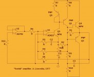
Here is an amp that I designed back in 1977. It works in class A+C. Class A part, single ended, is represented by a couple of transistors, Q1 and Q3, as a CFA amp. It outputs through a resistor R1. When voltage drop on that resistor is enough for 2 more transistors Q2 and Q4 to start acting, they gradually increase their current output, gradually entering class C in parallel with class A single ended operation that continues up to the clipping.
Nested feedback loops through the opamp provide what is now called VFA. Also, due to a capacitor in feedback of the opamp loop, it acts also as a servo. Ratios of feedback loops were selected for the cleanest resulting sound quality.
However, opamps were Soviet 140UD8 as the fastest opamp with JFET inputs that was ever available to me then, I just took some that were available from LTSpice library to show the diagram.
Attachments
Last edited:
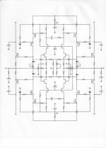
Here is one more, class A+B amp that I designed back in 197(9)? However, it is an output stage only.
Feedback to emitters of input transistors is provided by diodes, so when the amp is overloaded, their dynamic resistance gradually increases, and the amps on overload acts as a voltage to current converter. The sound resembled a tube amp. If "Swinnik" was used for a bass guitar in our rock group, this "Nuclon" amp was used for a solo guitar.
What bridge? No bridge, just a symmetric "CFA".
However, if you view diodes as transistors in LTPs with Beta=1, it may be viewed as a symmetric VFA.
Attachments
Last edited:
Hi Anatoliy,
Interesting spacers under the chips. Ours were white in colour and generally not supplied with the chip. Someone in the USSR was thinking back then.
I believe someone in USSR back then just ordered "To copy that damned thingies that we need for our military!"
Does it resemble anything? ;-)
Here is one more, class A+B amp that I designed back in 197(9)? However, it is an output stage only.
Would you be so kind to post the asc file also ?
Many thanks.
Patrick
Would you be so kind to post the asc file also ?
Many thanks.
It was drawn by somebody on this forum, from my pencil sketch. I don't have it.
I was never a fan of symmetric solutions, because I did not understand what is the point of minimizing of even order distortions only, by complicating the design, except at a big power when it can save some electricity. Yes, I did such exercises, for example bridging thick film ICs designed in our laboratory to get 200W instead of 50, but they did not survive my tests. My boss then examined them under microscope giving me more to try.
My boss then examined them under microscope giving me more to try. I will Only use symmetrical circuit topologies. Complimentary symmetry. You can get absolutely rock bottom distortion with zero or small amount of fb... CFB or VFB.
Why rock bottomer from symmetric topologies, and why zero or small amount of fb?
- Status
- Not open for further replies.
- Home
- Member Areas
- The Lounge
- John Curl's Blowtorch preamplifier part II