That's trivial - 12 inch in a foot > factor 12^3 either way
Edit: SY beat me to it.
Jan
It s not trivial since he didnt state the number otherwise than with a remaining division operation if i neglect the 3 power:
1/12^3.
Max
I use Dale CMF brownies. Based on power level and my measurements any contribution from these should be at least -300 dB re 1 V
DF,
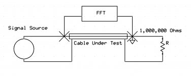
You are still confused about this. Why don't you find a colleague you trust and review the set up with them. For the convenience of anyone else who is confused I have included a revised sketch showing how a "ground" may be placed. Spice also gets confused without it.
It is more standard to use sweep tests for checking cable, so of course I use a different method. the cable behaves nicely with the tamed load. Now based on your very limited experience (") ) my woofer runs 50 to 200 hertz, the midrange 200-1000 hertz and the tweety bird does the rest and for some silly reason like atmospheric absorption requires the most power. Where do you think settling time would be most important?
) my woofer runs 50 to 200 hertz, the midrange 200-1000 hertz and the tweety bird does the rest and for some silly reason like atmospheric absorption requires the most power. Where do you think settling time would be most important?
BTY I have scads of "thick triax" left over in short (<500') lengths if you want to try a low impedance coax. Between shields it runs around 10 ohms or so I am told, never checked.
Now as SY is doing his best to confuse things.... Pipe is measured by the inside diameter, tubing by the outside! A piece of wood sold as a 2x4 is based on the size of the wood when cut green. It shrinks as it dries. So as different folks cheated a bit it was standardized as 1 5/8" x 3 5/8" but since the extra 1/8 confused folks it has dropped to the current 1.5" x 3.5" In my house I have all three sizes which makes some walls quite interesting. Also a problem when replacing doors as the walls are thicker than what the frame is cut to match.
I use Dale CMF brownies. Based on power level and my measurements any contribution from these should be at least -300 dB re 1 V
Measuring 1nV riding on 10mV means CMRR is an issue. Perhaps you don't understand what CMRR is? It is not just a spec for an instrument; it is a figure of merit for the whole apparatus.
DF,
You are still confused about this. Why don't you find a colleague you trust and review the set up with them. For the convenience of anyone else who is confused I have included a revised sketch showing how a "ground" may be placed. Spice also gets confused without it.
For thousand foot runs ala Ed, load spread vs frequency may be a more significant factor. That is why I wanted him to run settling time tests for the long run and load resistors ranging fro 4 to about 200.
John
It is more standard to use sweep tests for checking cable, so of course I use a different method. the cable behaves nicely with the tamed load. Now based on your very limited experience (
) my woofer runs 50 to 200 hertz, the midrange 200-1000 hertz and the tweety bird does the rest and for some silly reason like atmospheric absorption requires the most power. Where do you think settling time would be most important?BTY I have scads of "thick triax" left over in short (<500') lengths if you want to try a low impedance coax. Between shields it runs around 10 ohms or so I am told, never checked.
Now as SY is doing his best to confuse things.... Pipe is measured by the inside diameter, tubing by the outside! A piece of wood sold as a 2x4 is based on the size of the wood when cut green. It shrinks as it dries. So as different folks cheated a bit it was standardized as 1 5/8" x 3 5/8" but since the extra 1/8 confused folks it has dropped to the current 1.5" x 3.5" In my house I have all three sizes which makes some walls quite interesting. Also a problem when replacing doors as the walls are thicker than what the frame is cut to match.
Attachments
Last edited:
DF,
BTY I have scads of "thick triax" left over in short (<500') lengths if you want to try a low impedance coax. Between shields it runs around 10 ohms or so I am told, never checked.
The only thing that that will be measured in this "experience" is varability in the quality of the connection and the cable physical shaping when inverting the ends.
You could as well short an end and measure the RLC of the cable seen from one end or the other.
Saying that there s a directionality amount pretending that those numbers will be different depending of the shorted end.
You seem to be a bit confused. The triax bit is about an issue JN is having sending current pulses to a low impedance solenoid over a high impedance cable at high data rates.
The item you seem to be confusing it with is the limits of circuit theory. That is what the main cable test posts are about. To see if others get he same results under extreme conditions.
.......every cool kid knew that there was 28 grams in an ounce, except in New York, where there was 25.

Every cool Aussie kid always had 'correct weight' in his pocket.
Dan.
No confusion at this end. Your revised diagram now has the coax outer (with significant stray capacitance to everything else) carrying a voltage signal much higher than the one you are trying to measure. You can't always turn a bad experiment into a good experiment just by moving the ground connection.simon7000 said:You are still confused about this. Why don't you find a colleague you trust and review the set up with them. For the convenience of anyone else who is confused I have included a revised sketch showing how a "ground" may be placed. Spice also gets confused without it.
You seem to be a bit confused. The triax bit is about an issue JN is having sending current pulses to a low impedance solenoid over a high impedance cable at high data rates.
The item you seem to be confusing it with is the limits of circuit theory. That is what the main cable test posts are about. To see if others get he same results under extreme conditions.
For sure we can measure something but then is the data really displaying the characteristic you re talking about.?.
Before trying anything and since i cant prove you wrong then please explain what would be the mechanism behind this stated directionality, i would imagine that if it exist then you have an explanation.
1 g = 15.43 grains
1 grain = 64.8 mg
1 mL = 16.23 minims
1 Minim = 0.06 mL
1 oz = 28.35 g
1 lb = 453.6 g (0.4536 kg)
1 kg = 2.2 lb
1 fluid oz (fl oz) = 29.57 mL
1 pint (pt) = 473.2 mL
1 quart (qt) = 946.4 mL
Ohaus scale company was loving it, those triple beams were everywhere. Now if you had one of the veneer dial scales not many had any idea what you were putting on them! Except for the geeks who took chemistry classes not many had any idea what a balance was
No confusion at this end. Your revised diagram now has the coax outer (with significant stray capacitance to everything else) carrying a voltage signal much higher than the one you are trying to measure. You can't always turn a bad experiment into a good experiment just by moving the ground connection.
Really? Care to run some numbers? If you think it makes a difference then move the resistor to the other end. You were arguing PSSR now your target has moved. You really should have a chat with someone.
Pipe is measured by the inside diameter
http://www.simplifiedbuilding.com/images/uploads/PrintablePipeChart.jpg
http://pipeandhose.com/taxonomy/term/6
For sure we can measure something but then is the data really displaying the characteristic you re talking about.?.
Before trying anything and since i cant prove you wrong then please explain what would be the mechanism behind this stated directionality, i would imagine that if it exist then you have an explanation.
The issue in audio is that people notice something and try to explain it often with silly explanations.
The directional issue does show up in other areas where there are extreme conditions. I am asking to see if anyone else gets similar results. That is the first step, then once a theory is proposed comes the task of testing it.
I certainly can come up with many possible explanations. As previously mentioned it may be caused by trolls trying to collect a toll from the passing power. Scott seem to thick it was Maxwell's demons. Of course that was intended as humor!
Last edited:
Last edited:
1 g =
Next time I order a drink in the US, I'll ask for a 1/6585 cuft shot of bourbon.
Hi Ed....if you use a 1/3 octave noise source centered around 3,000 hertz of less than .01 volts RMS and limit your FFT to say 1,000 to 7,000 hertz and around 32K samples or more and do perhaps 16K averages at the same time as you use your second channel to monitor your noise source you just might see some interesting differences from directivity. You can also turn off you signal source to see the noise baseline. Now what is going on and is it at a level that is perceptible? Don't Know!
Now I think most of the stink is when someone observes something and offers an unsupported or even silly explanation for what is happening. So my first toe dip in the water I think showed that a few folks around here don't really get it. Others are interested and a few might actually try things to compare notes. That is what I think DIY is about.
I have done extensive AB listening over the last day or so, using a common 3.5STM-3.5STM connecting cable.
Three different sources (2 x Mobile phones playing Flac files and $1.00 eBay mini Mp3 player) feeding four different amplifiers (Sony shelf system, 3 x car stereos) with 3.5mm inputs.
I find that such cable is quite strongly directional, with the subjective result being differing depth imaging and perceived distortions according to the interconnecting cable direction. PM me for more.


Example pics, I believe the cable came with a Logitech system...I have not opened the cable to see what's inside.
"When the facts change, I change my opinion;", someone said, "what do you do?" You moved the ground; that moved my "target". The main problem is still there: measuring a small signal in the presence of a much larger signal with a similar spectrum.simon7000 said:You were arguing PSSR now your target has moved. You really should have a chat with someone.
I am chatting to lots of people. Most of them agree with me that your experiment is a bad one. I find that encouraging, as some of them know far more about good experiments than I do. If a simple theorist like me can see the flaws in your setup then it can't be very good.
Why don't you just drop this? You have adequately illustrated the point I made; for that I must thank you.
Jacco,
I don't often convert from English liquid measure to metric units, we do have just about everything I can think of marked in both units though. When I am working in distances I just have to remember 25.4:1 when going back and forth between inches and mm, not to difficult really once you get used to it. I have to do it all the time so it is second nature at this point. When I'm driving my car it always goes much faster in kilometers per hour! I still have to look at a cheat sheet for GD&T dimensioning but I'll get it down.
I don't often convert from English liquid measure to metric units, we do have just about everything I can think of marked in both units though. When I am working in distances I just have to remember 25.4:1 when going back and forth between inches and mm, not to difficult really once you get used to it. I have to do it all the time so it is second nature at this point. When I'm driving my car it always goes much faster in kilometers per hour! I still have to look at a cheat sheet for GD&T dimensioning but I'll get it down.
The main problem is still there: measuring a small signal in the presence of a much larger signal with a similar spectrum.
Loop. That only pollutes things further.
There are far more ways of designing a poor experiment than designing a good one, and one indication of the former is reluctance to provide details or R&R. Idiosyncratic definition of terms is also a red flag.
Aha, there's your problem.It is more standard to use sweep tests for checking cable, so of course I use a different method. the cable behaves nicely with the tamed load.
A sweep test is pseudo steady state. It will only measure the steady state response. It cannot tell you about the cable to load interaction for time varying (squared) waveforms, which is what audio actually is.
The settling time will give you a look-see at how the system responds to changes in the time varying signal. Every change in the frequency or amplitude of a time varying signal will cause end load deviation from the intended signal, and it will take the "settling time" for the load signal to return to the intended signal.
This is temporal distortion. It cannot be seen by a sweep, unless the sweep is moving so fast that it happens faster than the settling time.
Ummm, where we can hear it???Now based on your very limited experience (
Was that a trick question???
Seriously, the settling time variation has to be faster than the human ITD thresholds, then it doesn't matter. The whole kittencaboodle can settle in a day for all it matters, jsut as long as every frequency settles within 1 or 2 uSec of each other where we can hear the delay interchannel.
Danley does this using the multipass mike/playback thing.
Thanks for the offer. I have a spool of it on the production floor, it's pretty large, like 400 or 500 pounds of it on a 3 foot diameter spool (or coffee table for geeks). As an aside, I had to laugh at your description of a 200 lb spool as "large"...we rolled a medium size spool onto a pickup truck from a loading dock, and the front wheels came off the ground.. (now what was that plan "B"?) It was a copper jacketed cable about 650 feet long and about 1.1 inches diameter, we use it for carrying 30 kiloamps DC.BTY I have scads of "thick triax" left over in short (<500') lengths if you want to try a low impedance coax. Between shields it runs around 10 ohms or so I am told, never checked.
John
Last edited:
- Status
- Not open for further replies.
- Home
- Member Areas
- The Lounge
- John Curl's Blowtorch preamplifier part II