I think the page number varies. The post number is more reliable.
This is my page 20:
http://www.diyaudio.com/forums/showthread.php?s=&threadid=71189&perpage=25&pagenumber=20
This is my page 20:
http://www.diyaudio.com/forums/showthread.php?s=&threadid=71189&perpage=25&pagenumber=20
Please Excuse the Interruption
Can anyone post the three schematics that Richard Perez posted way back on the original thread, post 563. There is a lot of reference to them in the following posts and the conversations are obscured without them. Please excuse my ignorance if there is another post that contains them - I hate to intrude, but I’m really impelled to. Sorry to say I just stumbled onto the original thread last week. I didn’t even notice how big it was until it closed and I had to remove my jaw off of my keyboard and put it back in my head. Truly phenomenal, must be a record of some kind. (801 pages-yikes!) Thanks.
P.s. In the mid 80’s John Curl helped me fix my Symmetry ACS-1 crossover with a phone call and a Xeroxed copy of the Repair Manual for the ACS-2. I was amazed and thankful at the time that the crossover’s designer would actually help a customer at that level. It’s still operating and is still my Audio system’s centerpiece. Thanks again!
Pps. I tried to email Richard (Justcallmedad) but I couldn’t – system said I had to post a few times first. I guess that ends my career as a lurker!
Unfortunately, the review of pages 20-30 or so will be difficult for many, because many schematics are not available. Still, most is there, enough for anyone, but 'lurkers, voyeurs, and cloners'. Amateurs, you can't reproduce this design properly, anymore than you can make a hi end sports car, just don't bother.
Hi John,
Rather than trying to copy your work, I'm sure most people simply want a reference so they can understand better what you refer to.
Is it at all possible to scratch out something "not as good", post the diagram and talk about your concepts that way? Your interests then remain protected.
-Chris
Rather than trying to copy your work, I'm sure most people simply want a reference so they can understand better what you refer to.
Is it at all possible to scratch out something "not as good", post the diagram and talk about your concepts that way? Your interests then remain protected.
-Chris
Sorry, I supposed that why I lurked - nothing to add but lots to learn.
Anateck – exactly.
I certainly respect your opinion Mr. Curl. Actually I thought the schematics were posted and created by Richard Perez (Justcallmedad). Sorry. You said back in post 245 and more or less repeated at least once since:
“…The JC-80 would be a good candidate, but the output fets are not available to anyone, anymore. In fact, most of my best designs use difficult to find or obsolete fet's. It seems that only Erno Borbely and I have any stock of these fets and Erno sells them to audiophiles at a high price. I would too, if I were to sell any.
This poses a bit of a dilemma. If I publish specific circuits, then I will be asked by audiophiles around the world to 'help' them find parts, etc. This creates an almost impossible situation, so I would prefer not to do it. I hope that this explains my reluctance to publish my circuits, especially on a DIY website.”
Perfectly reasonable and understandable point of view and that is easy for me to accept. However it is hard to follow the logic when the words reference a picture that is no longer there. Too bad, great discussion, very valuable to understand with more insight than I can acquire on my own.. Oh well…
Hi John,
I don't mind helping you with that, if possible. I'm sure there are no shortage of people you trust to assist as well.
Send to bhome at sympatico dot ca and I'll resize it if required. I don't have a hosting site though. I don't even really know how that works.
Hi Audioford,
If you post a project, you are in no way responsible to guide people in part selection. As long as you try to use common parts, I can't see any problems. Besides, there are many members who can help. I would suggest "Google" first, or the manufacturer's web site.
There is a big difference between a basic amp, an amp from a data sheet and a device that was developed with such high participation such as the Symasym. (use the search feature). All you are expected to do is list the parts you did use. If you designed a PCB, post that also, or link to a place where the image is hosted.
-Chris
Edit:
Hi SY, the site was unresponsive for a bit before you posted. Either way, problem solved.
John,
If it's of any help, I have a website where I can put anything you may wish.
Just email me.
However, I feel it isn't good idea to publish BlowTorch schematics. May be without part names and values would be better, so that the topology may be discussed. I believe no one here wants to see within few weeks on eBay some Hong Kong DIY merchants offering BT "copies" (as they do to other well known amps).
If someone in Kong Kong wants to sell milled aluminum blocks at the cost of the raw aluminum I'm ready to send prints. If it has a bad kludge copy of a BT or a Ayre I'll toss the guts if I need to. I will know what I'm getting. (Recycled cylinder heads. . .)
The cost of getting metal machined in the US in small quantities is vastly higher than Asia usually.
The cost of getting metal machined in the US in small quantities is vastly higher than Asia usually.
Last Time...
Opps – Correction and sorry if I stepped on toes, the post by Justcallmedad was post 565 NOT John’s 563 post. Very sorry for the mistake. The link that doesn’t work is "LM317/337 datasheet example". There are a lot of specific references to the three examples in that post. Of course, who wouldn’t love to examine John’s work in detail, but I’m satisfied just to understand what is being shared as are many. It’s certainly more difficult without the once published picture to follow the logic. That's my error for not paying attention.
I currently don’t have time to breadboard anything these days. The virtual breadboard looks interesting. Besides, my experience was with PS’s and Digital Logic in the 70’s and 80’s, then it was OS software and applications, then Network design and now I’m in Network and Internet Security. I wish audio design was part of my repertoire, but not. Besides, to be really great at anything requires dedication, sweat and an enormous amount of time. Talent helps too! A number of those qualities are obvious in quite a few of those who post on this thread. Thanks for your patience, I’ll go back to lurking now…
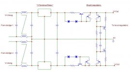
"No, after! The great advantage of a shunt is that it lets you localize the return current, rather than running it back through the ground wire to the supply input, with the risk that it contaminates the signal ground. "
Good point. If you keep th e shunt localized (i.e. around th e imeadiate gain stage), th e great benefit of this is the reduction in ground line noise.
I think if you drive the shunts with a constant current source, rather than a voltage source and dropper resisters, you get further bennefits.
Good point. If you keep th e shunt localized (i.e. around th e imeadiate gain stage), th e great benefit of this is the reduction in ground line noise.
I think if you drive the shunts with a constant current source, rather than a voltage source and dropper resisters, you get further bennefits.
john curl said:Oh, a voyeur!
Me too for a while, in my own personal Texas. I apologize to all the members here and the mods for losing my temper last week.
Bonsai said:
I think if you drive the shunts with a constant current source, rather than a voltage source and dropper resisters, you get further bennefits.
True, but the current source has to be as good (HF wise) as the regulator itself. Otherwise, stay with a resistor, it's better. A LM317 connected as current source is fair, but a LM337 on the negative side is a disaster.


- Status
- Not open for further replies.
- Home
- Member Areas
- The Lounge
- John Curl's Blowtorch preamplifier part II