OK. In this thread satire and reportage are indistinguishable, and I am afraid I sometimes forget who wears which hat.
Not to worry--this thread is for entertainment purposes, right? Engineering speak seems to happen more by accident.
")
Sometimes we have to train someone and that is always interesting. I have a friend who was my apprentice when I worked as a tool builder/ pattern maker in aerospace. I picked him out of a line of workers as I observed his work and how he worked. Before you knew it he was matching my skills, he was the correct choice. He still calls me over 8 years later when he has a problem and doesn't know the solution, I can usually talk him through the problem or tell him what he needs to do. We have remained friends to this day.

Oh, i understand better now. (i forgotten the story)I offered to do his PCB and that's how he treated me....
Sorry, but you asked for a lot of things i don't even understood, yes. Indeed.
It is strange, but Alex don't asked-me nothing, and the circuit worked...with no modifications of the schematic (about your " full of errata").
And, anyway, nobody is perfect.
At the beginning, it was just a project.
I provided the idea, then a schematic, added more features on demand and, some times after a BOM. Rome was not build in one day.
May-be you were too early in it ? We exchanged with Alex may be-3 emails. It seems he had no problem on his side.
At the end, i believe it was a lot of misunderstanding between us. I respect enough artwork to think any board designer (including-me at times) can understand the circuit he want to work on, know better than I the size of very ordinary components on the shelf, resistances, standard analog ICs that he has in his libraries etc... Not my position to treat a board designer as a single executant.
In my mind, it was a community "cooperative work", so i don't wanted to be "directive". And I'm out of the business since so long time: i thought you were better than me with components providers. That you had feel "lazy" ?
The project was not "free work for him (me)" (this protection was working yet in my system for years) but for the community.
I had spend a lot of time to answer your questions the best i could, all doors opened, anybody can makes his opinion here:
http://www.diyaudio.com/forums/solid-state/221737-ultimate-amp-protection-circuit.html
Sincerely, counter culture, I still do not understand today what i could do more for us at this time.
Misunderstanding, nothing more. And, anyway, i feel graceful for your help offer, even if it has not been achieved.
Can-we go back in the dedicated thread to speak about and try to be friend again ? There is so much variations we could do on it ? A miniature SMD version, as an example without all the options. That i'm unable, believe-me, to do by myself, too old for those martian components ;-)
Last edited:
Let's talk engineering:
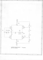
I am going to start with a sample of what I often use as a phono input stage. It is simple, but it is elegant as well. Let's go through it as 'engineers', piece by piece. You know, the good, bad, and elegant! '-)
Coincidentally, I have an SCP-2a sitting on my bench for repair.
It seems obvious that, for a tweeter, there is a difference in the energy it receive if you feed-it with square waves instead of rounded ones.
Even if it is not able to follow the slew rate, it will accelerate harder.
I wonder why some could pretend that we need 0.0001% of distortion on one side, and pretend this difference in speed we can see is not perceptible.
Now, did the sources able to provide such square waves ? With analog tapes recorders, i have a doubt. With digital, it is possible, depending of the anti aliasing filters.
On my side, am-I crazy ? I take great care to the slew rate of my amps.
In the eighties I owned a Revox A77 Tape recorder - not the worst of its time. And yes, one day I recorded a 1kHz square wave with it (2-track, 19cm/s). The playback signal viewed with an oscilloscope was really disappointing with ridiculously slow slew rates and really far away from the squareness of high-end power amp output at that era.
Maybe this is the origin of my sceptizism concerning published waveforms. High slew rates look nice, but are they a valuable indicator for fine listening experience? I do not believe that.
I repair them too, SY. Good luck!
Thanks. The circuit looks pretty straightforward, so things should be easy to trace down.
Who knows ? I just noticed little by little that the amps I preferred in my life were near always the fastest ones, lest often the ones with littlest distortion numbers at 1KHz.High slew rates look nice, but are they a valuable indicator for fine listening experience? I do not believe that.
Last edited:
voltwide,
I still have one of those ReVox A77 tape machines sitting on a shelf. I don't think I would have ever considered using it to record a sq. wave. That is about as useful as people testing speakers with sq. waves, not very relevant to what you are looking for on either end. The A77 was actually a fairly good sounding tape deck for a consumer tape deck.
ps. I know someone like Richard will say he uses sq. waves when testing the crossover for alignment but that is about all I would consider a sq. wave and a speaker for.
Last edited:
Oh, what a good idea.Let's talk engineering:
I am going to start with a sample of what I often use as a phono input stage. It is simple, but it is elegant as well. Let's go through it as 'engineers', piece by piece. You know, the good, bad, and elegant! '-)
One suggestion. Concerning PSRR and distortion. CSS to replace drain resistances ?
And a question about the need to pair active devices (expensive).
Analog tape recording is more exotic than you realize, voltwide. What you are seeing is: Phase shifting in the high frequencies, AND a finite rise-time due to a resonant reproduce head. You are NOT looking at slew rate limiting. Trust me on this. It is necessary to put in phase compensation to improve the look of the square wave, but it is exotic, and was not done in the early days. Rise-time limiting is NOT slew rate limiting. You were mislead in your looking at these waveforms.
Brianco, I am not arguing here, just pointing to an observation that has
been made many times by orchestral conductors. They have been exposed
to loud music all their lives and also suffer the loss of hearing too.
Strangely this hearing decline has not hindered their ability to hear the
music and point to instruments, musicians, choir that are performing
slightly out of tune, off key, or not correctly.
We can perceive far more than testing give us credit for.
A conductor is always ahead of the music...for by far the greater part he is directing a future event rather than reviewing a past event. Most will say that they can 'hear' that which is yet to be played before it is played. Similarly, composers often in the first instance put their music - or at least parts of it, straight to paper without having heard even a phrase played.
I wholeheartedly agree with your last statement!
My main points in my first post on this are that there are two types of 'audio' enthusiast: those for whom the music is more important than the equipment and those for whom the equipment is the more important. I know a few designers of retailed amplifiers and speakers and there is a similar split between them..except that profitability has to be their paramount consideration, and is responsible for shortcomings be they subjective or scientific!
The second point is that although I agree with Esparado's sentiment, Jacco has summed up the reality in succinct form.......most of us simply cannot hear well enough to be hyper-critical. The consequence is that I believe that there is far too much BS here..from both sides.
Ok, let's look into this circuit with more detail:
First, it is a potentially VERY quiet input stage as both input devices are in noise PARALLEL, not noise SERIES like a diff pair.
Second, the circuit has little or no cap multiplication, because the second stage is actually a cascode of the first stage.
Third, the complementary circuitry will attempt to null out the even order harmonics developed by the input stage.
Fourth: The dynamic range of the input stage can actually be extended by using even higher voltage power supplies, if necessary.
This is the essence of the Vendetta Research input gain module. It has been very successful for more than 30 years.
Later, I will address the 'downsides' of using this sort of circuit. But let's discuss the circuit, in general, first.
Attachments
- Status
- Not open for further replies.
- Home
- Member Areas
- The Lounge
- John Curl's Blowtorch preamplifier part II