I find these sonic differences between two 'well designed' amps to be the real question. Why? Of course, I have my own ideas, why, but I just can't convey them without a lot of static. '-)
Just say it and be done
")
Actually I think looking at distortion spectra of amplifiers and how that changes under adverse conditions can be quite revealing but I suspect there is far more to it than that... far more as in what translates to a great overall sonic result. High open loop gain, immunity to RF appearing at the speaker terminals (ever scoped across an unterminated speaker and its leads ?) and good behaviour in the presence of voltage fed back to the output... those big speakers also make pretty pokey microphones too.
I'm currently working on a new power amp that majors on high current delivery and ability to drive low impedance loads rather than high traditional xx watts/8 ohms. How it will all work out... lol, well I'm not quite sure but the initial results are promising. The design has high open loop gain but runs with a very low feedback factor when judged against typical designs. It is designed for class ab (I'm not a class A fan) but the results when it is biased into class A are pretty decent too.
Attachments
I think we have to understand a given amplifier's response to having varying amounts of power rail variation with signal current, to have any hope of understanding the effect of more or less rail capacitance. That is---what is the power supply rejection behavior? One can make amplifiers have a whole lot of PSR, even out to and including the output stage. Of course things will fall apart when the output voltage swing gets close enough to the hard limit, so we hope we don't get all that close, or we prevent it by doing some active level reduction ahead, perhaps based on the rail voltages at a given moment (I've done this with cheap stuff and it can work fairly well).As you probably know, I too am a big cap fan. However, I must note that practice shows that it's not all in the caps, and amps having seemingly modest caps still manage to pump out enormous currents, albeit in short term bursts only. This begs the question where does the big current live, in the big caps or in the concept and execution?
A good example would be my wife's H/K 680 integrated amp. It is nominally rated at 85/130W into 8/4 Ohms, it is also a dual mono design, one trafo but separate windings for each channel, separate bridge rectifiers and two 8,200 uF caps per channel. True, this is capaity wise inside your above specs, had it ben a single source PSU it would have had 2*8,200 uF per PSU line, or 16,400 uF per PSU line. Still, by modern standards I'd call that a modest PSU, yet the amp doesn't seem to lack oomph even into 2 Ohms, into which it will deliver just over 500W in peaks (t=20 mS, IEC stadards).
If the caps had been bigger, say 12,000 uF each, it would probably do even better, but I think you'd find that despite a formal +46.3% larger caps, the actual net gain into say 2 Ohms would have been more like 5-15%, or something like that. The gain would have been bigger in quality rather than quantity. Unfortunately, it's anything but a linear funtion. In my view, it's much more about the capacbilities of the electronics rather than simple cap size, even if bigger certainly can't hurt.
Although the famous NAD 3020 is hardly the audiophile's epitome, it has a fairly high-impedance power transformer and modest rail filtering. This means it is also self-protecting, most of the time---to increase the bulk caps can provoke a dangerous situation for the two output devices per channel (usually the PNP is the most vulnerable). If you know not to push it too hard, you could probably get along and maybe hear some performance improvement. But the machine manages pretty nicely with the stock design, considering the cost, in part because the power supply rejection is fairly good.
Ok, so what amp will sound better?
They are both CFB with same OPS but first have single ended gain stage, and second have complementary gain stage. They both have 40dB of global feedback and fundamental F is 1KHz +27dB.
Who knows? At 10Amps while fighting blind-currents and delivering 30 Volts in a non linear load, eating the counter-electromotive force generated by the loudspeaker, while connected by a cable exhibiting inductance, resistance and capacity, it all uncontrolled (except for that exceptional amplifier
) by the designer of the amplifier (he did not select the load and the cable, or the source and it's impedance). Who knows!
Last edited:
At what fundamental frequency, at what SPL, it's all different.
your choice. Find your most sensitive conditions and report that result.
-RNM
Last edited:
You know, Richard, it is almost impossible to put a number on distortion detection without knowing the properties of the distortion.
We are told that 2'nd harmonic distortion is roughly twice as easy to listen to, so how can we use that as a reference?
Over the decades, working with analog recording, I found that HIGHER ORDER distortions, created often by Xover distortion in preamps and amps, and clipping the record amp were truly audible.
"We are told that 2nd....." Thats a problem.... the mysterious 'someone else said this or that and we use it as if it applied somehow to me/you or the situation.
Still need a number from each person... what is your number? --- the situation is up to you... but what is the condition and how low can you detect "it". --- the situation which gives the most sensitive level of ______ that you can detect?
THx-RNMarsh
Remember that the Sansui has a single PSU, one for both channels.
As does the HK6550. (it's two times 13,000 uF btw. ~34J for the both of them)
Comparing apples to oranges, the Sansui has balanced output stages.
(the designer of the alpha-x models was so dead set on tackling ground noise issues that he introduced a fundamental flaw, imo)
As does the HK6550. (it's two times 13,000 uF btw. ~34J for the both of them)
Comparing apples to oranges, the Sansui has balanced output stages.
(the designer of the alpha-x models was so dead set on tackling ground noise issues that he introduced a fundamental flaw, imo)
Sorry Jacco, I know the official schematic says 13,000uF, but I also know what I took out and replaced it with, in both cases 15,000 uF. Which, BTW, I purchased from Harman as spare parts.
I think we have to understand a given amplifier's response to having varying amounts of power rail variation with signal current, to have any hope of understanding the effect of more or less rail capacitance. That is---what is the power supply rejection behavior? One can make amplifiers have a whole lot of PSR, even out to and including the output stage. Of course things will fall apart when the output voltage swing gets close enough to the hard limit, so we hope we don't get all that close, or we prevent it by doing some active level reduction ahead, perhaps based on the rail voltages at a given moment (I've done this with cheap stuff and it can work fairly well).
Although the famous NAD 3020 is hardly the audiophile's epitome, it has a fairly high-impedance power transformer and modest rail filtering. This means it is also self-protecting, most of the time---to increase the bulk caps can provoke a dangerous situation for the two output devices per channel (usually the PNP is the most vulnerable). If you know not to push it too hard, you could probably get along and maybe hear some performance improvement. But the machine manages pretty nicely with the stock design, considering the cost, in part because the power supply rejection is fairly good.
Agreed - no argument there. I am blessed by my hard core approach to always use split supply lines, with those for the input stage(s) regulated by the simples form of regulation possible 5-7V above the current stages supply lines. I've done it like that since 1979 and never looked back. Having a dual supply system enables me to do some extra filtering of the IPS and VAS, an opportunity I never miss. First the bridge, then the first 2,200uF cap, a series 10 Ohm rsistor, then the second 2,200 uF cap bypassed with 100 nF, then a zener assited cap multiplier, followed by yet another 2,200 uF cap again bypassed by 100 nF. Never failed me yet, and boy oh boy, was I ever so pleased when I discovered that Krell also used the same circuit for the same purpose in their older amps. If money is no object, I throw in a discrete 12 or more (depending how much current I need, proper full regulator, but I haven't done that for years now. No need.
Fofr the current stages, where I know I wll need a lot, I always use several capsin parallel rather than single values. Typically, I put 2*10,000uF per supply line (40,000 uF per side), do a bit to filter it all, and then throw in a 2,200 uF cap as near as I can bring it to each and every output transistor in the output stage, in my case, 3, 4 or 5 pairs. Sure, it takes up its fair share of PCB real estate, but more than makes up for it in sheer speed and immediacy. And I typically end up with a total of 28,200 per every power line (for four paoirs of my beloved MJL 3281/1302), or a very nice 56,400 uF per side. Since my voltages rarely exceed +/-56V at full PSU load, that gives me about 44 Joules of energy per side. Turn on delay mandatory.
As does the HK6550. (it's two times 13,000 uF btw. ~34J for the both of them)
Comparing apples to oranges, the Sansui has balanced output stages.
(the designer of the alpha-x models was so dead set on tackling ground noise issues that he introduced a fundamental flaw, imo)
All very nice, Jacco, but in the end, that small H/K portrays music better, and not by a small margin, than that technically perfect Sansui. And the odd thing is that it runs circles around the Sansui in bass registers, sounding more enegetic and lively than the 3dB more powerful Sansui. A smaller advantage to H/K in the midband, in the treble there's hardly any difference to speak of. Equally unfortunately, this makes the Sansui's sound to be less convincing and be a little coloured, due to imbalance between top and bottom. Its top end is just fine, it's the lack of bass that's doing it.
One thing I didn't mention as it is fairly obvious: the real behavior of the output devices with demanding loads must be well-understood, and their drive circuitry be able to supply adequate current. Sometimes it appears there is an excess of paralleled output devices in some good designs, but although their collective power dissipation may seem over-the-top, the beta falloff at high currents and at low Vce (supposing bipolars in this case) means a whole lot more base current than for more benign signals and loads is required. At the same time there's a need to avoid saturation and attendant cross conduction or "shoot-through". And be careful not to exceed the base current ratings.
One of the things that Richie Miller and Marty Zanfino did for some of the better-received h/k products was to test with the "power cube" and in some cases actually publish the results. This machine would explore the whole range of load conditions conceivable at least as resistance and reactances, within the design limits, and the closer one came to a rectangular display the better.
When I inherited an automotive amp (supposedly all finished except for a few little details ) designed in Northridge, for whom the tough customer was h/k, I had to show that the beast could drive highly reactive loads. I recall that the inductor I borrowed from the speaker lab had to be immersed in water to cool it for even brief tests. This was the TC600, which had a number of the Toshiba 2SC3281/2SA1302 parts in the output.
One of the things that Richie Miller and Marty Zanfino did for some of the better-received h/k products was to test with the "power cube" and in some cases actually publish the results. This machine would explore the whole range of load conditions conceivable at least as resistance and reactances, within the design limits, and the closer one came to a rectangular display the better.
When I inherited an automotive amp (supposedly all finished except for a few little details
) designed in Northridge, for whom the tough customer was h/k, I had to show that the beast could drive highly reactive loads. I recall that the inductor I borrowed from the speaker lab had to be immersed in water to cool it for even brief tests. This was the TC600, which had a number of the Toshiba 2SC3281/2SA1302 parts in the output.DVV ,
Why do think I'm listening to a 250W H/K 680 right now (that can do 1/2Kw peaks).
I have the original 680 , gave it to my daughter. It beat the pioneer's , sansui's
all the other mid-fi that has passed my bench by. (I kept the H/K - it stood out).
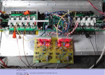
PS - here is a HK !! (below)1/2 KW of 680 OPS's shaking the house
powered by a 400V/uS CFA - Blasphemy !
OS
Why do think I'm listening to a 250W H/K 680 right now (that can do 1/2Kw peaks).
I have the original 680 , gave it to my daughter. It beat the pioneer's , sansui's
all the other mid-fi that has passed my bench by. (I kept the H/K - it stood out).
PS - here is a HK !! (below)1/2 KW of 680 OPS's shaking the house
powered by a 400V/uS CFA - Blasphemy !
OS
Attachments
Last edited:
I am happy that you know where the money is Jan.
I was in Wolfgang Klippels room at CES.
He had a pair of 1.5 liter boxes playing with his latest soft and hardware.
It sounded crap, sorry.
It just does not work.
Wolfgang and i then had a discussion about food and health.
I was in Wolfgang Klippels room at CES.
He had a pair of 1.5 liter boxes playing with his latest soft and hardware.
It sounded crap, sorry.
It just does not work.
Wolfgang and i then had a discussion about food and health.
I am happy that you know where the money is Jan.
I was in Wolfgang Klippels room at CES.
He had a pair of 1.5 liter boxes playing with his latest soft and hardware.
It sounded crap, sorry.
It just does not work.
Wolfgang and i then had a discussion about food and health.
Funny just 1/2 an hour ago I discussed WK's project with Bob Adams he said it was not hopeful.
Ok, so what amp will sound better?
They are both CFB with same OPS but first have single ended gain stage, and second have complementary gain stage. They both have 40dB of global feedback and fundamental F is 1KHz +27dB.
You must have the errors of the capacitors in your bode. LT can have a
-160 to -200db noise floor.
You need a "keentoken" lesson
.OS
Just say it and be done
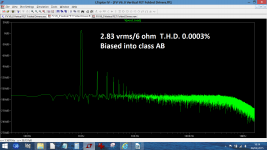
Actually I think looking at distortion spectra of amplifiers and how that changes under adverse conditions can be quite revealing but I suspect there is far more to it than that... far more as in what translates to a great overall sonic result. High open loop gain, immunity to RF appearing at the speaker terminals (ever scoped across an unterminated speaker and its leads ?) and good behaviour in the presence of voltage fed back to the output... those big speakers also make pretty pokey microphones too.
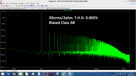
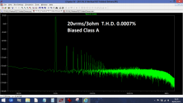
I'm currently working on a new power amp that majors on high current delivery and ability to drive low impedance loads rather than high traditional xx watts/8 ohms. How it will all work out... lol, well I'm not quite sure but the initial results are promising. The design has high open loop gain but runs with a very low feedback factor when judged against typical designs. It is designed for class ab (I'm not a class A fan) but the results when it is biased into class A are pretty decent too.
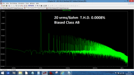
What MOSFET models are you using , those HF artifacts in class AB are
excessive.
Most BJT class AB simulations will give a cleaner output (below - 40Vrms).
You DO have your noise floor down , but the real life devices will most
probably perform better
Cordell or keentoken might have some superior models.
OS
Attachments
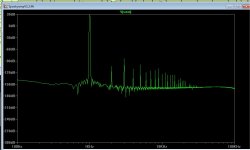
Ok, so what amp will sound better?
They are both CFB with same OPS but first have single ended gain stage, and second have complementary gain stage. They both have 40dB of global feedback and fundamental F is 1KHz +27dB.
They both may have similar levels of feedback but the first one has 7x more H3 than the second one, even though H2 is dominant.
The first amp has much less open-loop linearity, regardless of the quality of the harmonics. You could say it has a harmonic generator in it. You could achieve the same effect by using an SE buffer in front of the second amp. How do you know the first amp doesn't have all the harmonics of the second amp, just hidden by the harmonics being generated?
So it's a lopsided comparison. There do exist situations where SE and symmetrical circuits produce highly identical harmonic results, simply because they are not the dominant sources of distortion.
Also, try choosing the Hanning or Blackman window in the FFT dialog to get the noise floor lower (smooth noise floor = spectral leakage from rectangular FFT window).
Last edited:
Cordell or keentoken might have some superior models.
OS
This is the space to watch:
http://www.diyaudio.com/forums/software-tools/266655-better-power-mosfet-models-ltspice.html
Modern Lfet models are on their way, but very slowly as the kinks are worked out of the modeling process. Cordell has already posted some IRFx240 models.
- Status
- Not open for further replies.
- Home
- Member Areas
- The Lounge
- John Curl's Blowtorch preamplifier part II