Speaker and current distortion... this is why voltage drive works, when you look at the air load behind the speaker membrane it varies both in direction and magnitude with displacement, acceleration and velocity. This capability to deliver current on demand is to my knowledge the area where the greatest difference in amplification is buried. When measuring steady state through a resistor in order to determine a distortion profile you only see a fraction of the working conditions of an amplifier. when you measure with a real speaker the picture gets a little better, but in reality the only useful measurement would be withe a transient signal and a real load. Then is suspect we see more of a understandable difference between amplifiers
Pavel
I ask for the 0dB in Volts, as I focus on the relative amplitude of the harmonics for to do the (non linear) impedance estimation.
George
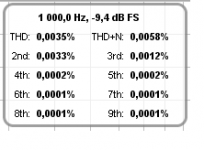
George, every of those plots has a chart like attached, in the top left corner. 2nd and other harmonics are related to the base frequency amplitude but the reading in % is absolute. % distortion reading does not depend on dBFS base frequency amplitude of the plot. You can also read the base component amplitude in dBFs. Amplifier output was 1.414Vrms. Measured with independent instrument. I am sorry but I have not fixed (calibrated) the plots to 0dB, however, the distortion lines are always relative to base frequency amplitude and from these data and 1 ohm resistor you must be able to get what you need.
As an example, 6th 0.0001% says it is -120dB below the base frequency amplitude. But it is better to read from the plot directly vs amplitude in dBFS (here - 9.4), chart is unable to tell less than 0.0001%.
Attachments
Last edited:
Yes Pavel
This is what I would like to do, but I need some confirmation over the 1kHz amplitude.
I read that the amp output is 1.414V but you wrote that
“-10dB tap/divider was used for voltage measurements, no divider for current measurement”
so, I am not sure if this 1.414V is measured upstream or downstream of the divider.
In any case, you don’t have to worry about it.
I have the suspicion that the back EMF current flow makes the situation a bit complicated for an easy analysis anyway.
")
George
This is what I would like to do, but I need some confirmation over the 1kHz amplitude.
I read that the amp output is 1.414V but you wrote that
“-10dB tap/divider was used for voltage measurements, no divider for current measurement”
so, I am not sure if this 1.414V is measured upstream or downstream of the divider.
In any case, you don’t have to worry about it.
I have the suspicion that the back EMF current flow makes the situation a bit complicated for an easy analysis anyway.
George
Voltage spectral measurements (amplifier voltage and speaker voltage) are measured with -10dB divider activated. However, amplifier rms voltage was measured independently directly at amplifier output, as a reference, with a precise multimeter without any divider. So you take 1.414V rms (real ouput voltage) and assign it to base frequency line of the amplifier voltage2.png image.
Speaker current spectrum was measured as a voltage drop across 1 ohm resistor, without additional -10dB divider.
Speaker current spectrum was measured as a voltage drop across 1 ohm resistor, without additional -10dB divider.
Amplifier voltage is -9.4dB + 10dB = +0.6dB
Speaker voltage is -10.6dB + 10dB = -0.6dB
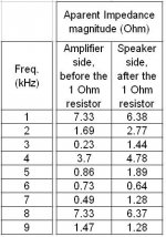
Speaker current (voltage at 1 ohm) is -16.7dB + nothing
Difference between amplifier voltage and voltage at 1 ohm res is -16.7 - 0.6 = -17.3 dB
1 ohm to 6.75 ohm divider is 20 log (1/7.75) = -17.8 dB
The error is 0.5 dB.
Speaker voltage is -10.6dB + 10dB = -0.6dB
Speaker current (voltage at 1 ohm) is -16.7dB + nothing
Difference between amplifier voltage and voltage at 1 ohm res is -16.7 - 0.6 = -17.3 dB
1 ohm to 6.75 ohm divider is 20 log (1/7.75) = -17.8 dB
The error is 0.5 dB.
Voltage spectral measurements (amplifier voltage and speaker voltage) are measured with -10dB divider activated. However, amplifier rms voltage was measured independently directly at amplifier output, as a reference, with a precise multimeter without any divider. So you take 1.414V rms (real ouput voltage) and assign it to base frequency line of the amplifier voltage2.png image.
Speaker current spectrum was measured as a voltage drop across 1 ohm resistor, without additional -10dB divider.
Very nice measurements, thank you for your efforts.
Vs = L dI/dt + I dL/dt + IR.
The inductance of a voice coil has a velocity component which is proportional to the absolute value of the coil velocity within the gap.
This will also be modulated by the conductance of the pole pieces.
jn
I have repeated the same measurement, with some loop issues fixed. The numbers are consistent and the 1st measurement is confirmed. Speaker current shows more distortion than speaker voltage. The speaker produces high harmonics at considerably higher level than those arriving from an amplifier.
Nice!
Your measurements confirm what Earl Geddes has been saying for years: that competent electronics present far fewer problems than speakers and room.
He used to demo his speakers using Pioneer consumer receivers, (VSX series, I think; chip amps, anyway), because he said they had no visible crossover distortion at low input levels and were otherwise competent for his efficient speakers. He got quite a bit of criticism from some audiophiles for doing this but was quite unbending.
I don't know what electronics he's using these days but I doubt he's changed his position.
Frankww,
You also must be aware then that Earl also says that compression drivers are commodities that are interchangeable with little to no real differences between devices. I think he holds that also for most large 15" speakers that they are all basically all the same and are therefore interchangeable with some slight FR corrections. Many do not agree with this assessment of the differences in distortion between common devices that do indeed show very different distortion profiles. Some things are just simplified to an extent that the differences are lost in translation.
You also must be aware then that Earl also says that compression drivers are commodities that are interchangeable with little to no real differences between devices. I think he holds that also for most large 15" speakers that they are all basically all the same and are therefore interchangeable with some slight FR corrections. Many do not agree with this assessment of the differences in distortion between common devices that do indeed show very different distortion profiles. Some things are just simplified to an extent that the differences are lost in translation.
It is the same old argument.
Can we hear amplifiers that have good distortion 'specs'?
After all, loudspeakers have so much more measured distortion. In the old days, and even today, vinyl records and analog recorders had so much more distortion also. We should have had 'perfect' power amps (except for absolute power) 40+ years ago. Yet, we still seem to hear differences in power amps, and EVEN preamps. WHY?
I was told that it was negative feedback and I have been looking at the problem ever since.
Discussed here today, I see IIM, first extensively discussed by Matti Otala back in 1978 or so. Want to see something really interesting? Use the speaker as a microphone, especially a horn. See what you get, and it is more than harmonic distortion. What does the amplifier do with this added input, and is the input stage designed to accept the added error signal with real music playing?
Want to see something really interesting? Use the speaker as a microphone, especially a horn. See what you get, and it is more than harmonic distortion. What does the amplifier do with this added input, and is the input stage designed to accept the added error signal with real music playing?
This is also to my point of where to look to make progress.
THx-RNMarsh
Frankww,
You also must be aware then that Earl also says that compression drivers are commodities that are interchangeable with little to no real differences between devices. I think he holds that also for most large 15" speakers that they are all basically all the same and are therefore interchangeable with some slight FR corrections. Many do not agree with this assessment of the differences in distortion between common devices that do indeed show very different distortion profiles. Some things are just simplified to an extent that the differences are lost in translation.
What relevance does that have to my last post?
Amplifier voltage is -9.4dB + 10dB = +0.6dB
Speaker voltage is -10.6dB + 10dB = -0.6dB
Speaker current (voltage at 1 ohm) is -16.7dB + nothing
This means that for voltage spectrums the 0dB is 1.3196V and for current spectrum 0dB is 0.4173A
The estimation of the impedance using the harmonic peaks from these FFTs wasn’t that fruitful!
I would say that, since voltage and current pick-up weren't done simultaneously, phase relation was random, so R=V/I doesn’t really hold.
Thanks again for your work.
George
Attachments
Use the speaker as a microphone, especially a horn. See what you get, and it is more than harmonic distortion. What does the amplifier do with this added input, and is the input stage designed to accept the added error signal with real music playing?
I assume the speaker is connected to the output not the input, and please put some numbers on this. Easy to do, drive one look at the other when I've used speakers as microphones I get mV levels out.
Once, long ago, I thought all 15"drivers were pretty much the same too. Perhaps some had a larger magnet structure to get more efficiency, but was it worth the cost?
Klipsch used an inexpensive 15" woofer in his K-horn in the 60's and 70's. Why pay more? The tradeoff was in using a 4 ohm speaker instead of an 8 ohm loudspeaker in order to make up some efficiency loss in the driver. Now, and even then, quality amp power, especially for K-horns was relatively easy and cheap to buy. Why waste it on a more expensive 15" speaker like an Altec or JBL? In his case, except for the lower drive impedance at frequencies below 400 Hz, there did not seem to be much of a problem, UNTIL he tried to use the same 15" driver as a direct radiator. Nominally it worked, but it just did not get the bass right. You see, one important way that an inexpensive speaker manufacturer might try to make up for less magnet, and wide tolerances is to make a 1:1 physical fit between the magnetic structure and the speaker voice coil windings. So, at moderate levels, all is OK (sort of) but when you really drive the cone, it falls away from the magnetic field more and more. So the distortion generated by the change in magnetic field intensity will cause even higher order odd harmonics, and the speaker will hardly move from its center location without a lot of drive. Pro speakers like JBL often 'underwind' their voice coils so that the magnetic field remains 'steady' even with some serious cone movement. Some manufacturers 'overwind' their speaker coils so that a certain percentage of the coil is in the magnetic field at all times. This approach has other problems, but it is an effort to address the issue and was first used by Acoustic Research in the 1950's, and used by many companies over the decades.
Now what if you compare a JBL speaker and the inexpensive speaker that I described in the same test enclosure? The results are different, even if the fundamental resonances are about the same, and the speaker cabinet is large and strongly built.
This difference in performance is what Geddes appears to be ignoring, but it is real, and I'm sure, measurable, and one important reason why many quality drivers are so expensive, they have to generate an even bigger magnetic field in order to make up for the losses created by 'underwinding' or 'overwinding'.
Klipsch got away with the inexpensive driver in the k-horn, because the bass horn limited the necessary excursion of driver, but in a box, the speaker became very compromised.
In addition, measurement at amplifier terminals (posted) shows what "sees" the amplifier from the speaker. Good to compare with current through the speaker. This is what "sees" the speaker. Blv is a function of current (Bli), the other components of speaker equation as well.
Last edited:
Geddes hardly uses "inexpensive" parts
I believe his idea of "commodity drivers" is that effectively equivalent features and performance drivers are made by multiple manufacturer's - not hand crafted by a singular boutique audiophile guru
and not just the cheapest part in the catalog that fits the hole in cabinet - just the few that meet his performance and feature criteria
much like saying Onsemi and Fairchild make some functionally equivalent output Q
Last edited:
- Status
- Not open for further replies.
- Home
- Member Areas
- The Lounge
- John Curl's Blowtorch preamplifier part II