2 cubic inches and about $10.
Times 10 for a preamp would make a nice combo with the glowing Tent power amp.
Sure would bring a nice red glow to the listening room on a Saturday night.
And not more than 5-15mA of load current, combined with a poor output impedance.
Circa 20 W in total for the whole preamp.
It could easily deliver more, but the cap x transistors need to be rated for higher current - 15032/33 for example.
Oh good, that's reasonable. Thank you, Bonsai.
And not more than 5-15mA of load current, combined with a poor output impedance.
Works fine at 30mA.
If you need lower output impedance, you have a pretty poor signal circuit.

Why not something a bit different and original for a change?
We always see the same old rehashed shunt regs fed by a CCS, but if they work in tandem instead of independently, it brings many benefits: reduced dissipation, better rejection, lower output impedance.
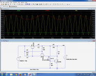
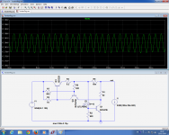
I tested the concept with this circuit: the shunt reg formed by D1 and Q1 works at ~10mA, and the CCS is servoed to keep this current constant.
Here, the sim shows the behavior with combined rippled input and an output current varying between 50mA and 150mA.
Performance looks interesting, even without any optimization or additional bypass caps
It has probably already been invented twice (at least) anyway....
We always see the same old rehashed shunt regs fed by a CCS, but if they work in tandem instead of independently, it brings many benefits: reduced dissipation, better rejection, lower output impedance.
I tested the concept with this circuit: the shunt reg formed by D1 and Q1 works at ~10mA, and the CCS is servoed to keep this current constant.
Here, the sim shows the behavior with combined rippled input and an output current varying between 50mA and 150mA.
Performance looks interesting, even without any optimization or additional bypass caps
It has probably already been invented twice (at least) anyway....
Attachments
Works fine at 30mA. If you need lower output impedance, you have a pretty poor signal circuit.
Poor output impedance -> poor regulation Ro = dVo/dIo For 10x red 5mm leds in series, that would be about 50-75ohm (according to a typical red led datasheet). That would be a 1-1.5V drop for a 20mA load. Really, anything that requires a better regulation is "poor signal circuit"? Those guys (TI, Linear, Analog) designing and manufacturing ultra low noise LDOs must be stupid, right?
If you don't care about regulation, why don't you use a raw power supply (xformer + bridge + large (1000uF/16V) electrolytic + ceramics). It would likely have lower noise, lower output impedance and definitely support more current.
Polypropilene are excelent caps, but according to many authors and Wima cap. manufacturer are bad solution for power supply decoupling. I understand that low ESR of PP caps is a bad thing for that duty. They suggest using polyester or multylayer ceramic capacitors instead.I got those values by trying and trying again. The need for the current limiting resistor is obvious. Initially, I threw in a 22 uF electrolytic cap, and it worked but the sound left something to be desired. Moved on to 33 Uf, 47 uF, etc and finally settled on 220 uF as nothing of audibility happened if that was further increased, at least that I could detect.
Then the 47/51/56/62/68 Ohm resistors came in and that made the whole still better sounding. But do remember, rather uncommonly I follow the circuit by yet another 2,200 uF cap in parallel with a 220 nF polypropilene; that kills HF noise dead. It them really starts to resemble a battery, assuming only that the following circuit current demands are met with a margin of error of at least 50% above the required minimum (I do twice the required minimum just for the hell of it).
It never oscillated on me, yet just to be sure I do throw in a 10 Ohm resistor to the base as a "gate stopper". No actual need, just to be double sure. Better to prevent from happening than to have to cure it afterwards if it does happen.
The reason why I use it by default is certainly not because it's the best one ossible, but because it literally never gets in the way. I never have the feeling of a lack of speed and dynamics, and after all, the cost of the whole circuit is quite reasonable overall, the 2,200 uF/80V dominate in price terms.
It seems you agree John. I should perhaps add that Krell used about the same circuit in the early 90ies, so I guess there's something to it.
Poor output impedance -> poor regulation Ro = dVo/dIo For 10x red 5mm leds in series, that would be about 50-75ohm (according to a typical red led datasheet).
It's somewhat lower than that; I measured 40 ohms at DC and about 18 ohms at 1kHz, with impedance dropping further as frequency increases. But if your circuit is class A (and I think that any preamp with pretension to quality is class A), then how does it matter?
More complex circuits can give a lower source Z at the expense of higher complexity and noise; that's why I use simple regs in my designs. Unregulated supplies have terrible line rejection. But I still can't wrap my head around the notion of designing lousy circuits, then going to heroic lengths to make super power supplies to make up for the deficiencies.
edit: my measurements were at 10 mA. At 30mA, based on the measured LED impedance for the devices I specified, the impedance is reduced by about 50%. Not that it really matters.
I havent seen any talk of an opamp in place of the C-multiplier transistor... low Zo etc. Is it applicable to the discussion??
View attachment 450649
THx-RNMarsh
See my earlier post in this thread. Better to separate clean voltage reference production and feed that into opamp with or without buffer to produce current on demand. Made some protypes a while ago, and you get to very low noise levels and Zout.
To have ultra clean power supply with highish Zou to me seems nonsense. Stuart remarked earlier that this should be sorted out by the subsequent circuit, but if that is so, why have an ultraclean ps to begin with? My sense is that usually, psrr of following circuit will be good enough to use bog standard circuit like lm317 or cap multiplier. However, I needed virtual earth for single supply Sallen-Key crossover. In this situation you need to sink and source currents, and all noise becomes a direct input.
I am trying to emphasize optimum power supply concepts, rather than details, so I have left off any 'absolutely unnecessary' parts, but the final design will have all the bypasses and protection necessary. We are just not there yet.
What are the criteria for optimum? Lowest noise? best volt regulation? Low Zo? Isolation from line side variation?
Dont those things change in priority with app?
THx-RNMarsh
Last edited:
I understand that low ESR of PP caps is a bad thing for that duty. They suggest using polyester or multylayer ceramic capacitors instead.
What we definitely do not want are resonances in bypass capacitors. L and C and ESR play the game. L means PCB track inductance as well. So, for someone maybe paradox, higher ESR or even resistance in series with bypass capacitor may help (R > sqrt(L/C)). Depends on real circuit and real PCB design!
Polypropilene are excelent caps, but according to many authors and Wima cap. manufacturer are bad solution for power supply decoupling. I understand that low ESR of PP caps is a bad thing for that duty. They suggest using polyester or multylayer ceramic capacitors instead.
There are basically two series of caps from Wima, MKT used for power filtering and MKS used for signals, and both have additional subcategories. While similar in frmat and base material, they are not the same.
I use MKT for power line filtering and MKS for signals, just as suggested by the manufacturer. Beside Wima, I might also use Siemens caps, and on occasion, Plessey caps.
I have been using Wima and Siemens from my first project in 1975, so we are old friends. Looking into somewhat older literature from the manufactuers, you will find that for example Kensonic Accuphase also uses the very same combination and in fact advertises it.
Inside the same series, they vary in voltages, size and even base material, so when buying make sure you have checked and rechecked.
Regarding tantalum, for smaller values, say 1 ... 47 uF, I have yet to see a better decoupling capacitor by anyone. Their problem is relatively low voltages at which they work, which is obvious to everyone. Less obvious is that the small drop types are not very reliable and can play tricks with you. However, they are relatively cheap. Much better quality will cost more and is available in block form from some reputable sources, such as say Roe(derstein). Good for zener diode filtering and things like that, not good at all for signals, I tried on several occasions and didn't like what I heard, bypassed or not.
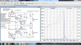
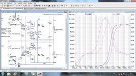
What we definitely do not want are resonances in bypass capacitors. L and C and ESR play the game. L means PCB track inductance as well. So, for someone maybe paradox, higher ESR or even resistance in series with bypass capacitor may help (R > sqrt(L/C)). Depends on real circuit and real PCB design!
This is example of my PS shunt regulator (I would like to see more practical examples, not just small doses from established audio designers, it will help us amateurs) where a low ESR bypass capacitor could show very narrow peak in the output impedance, but adding small series resistor(0.1R) show very nice output impedance. The caps in question, C1 and C5.
Attachments
What are the criteria for optimum? Lowest noise? best volt regulation? Low Zo? Isolation from line side variation?
Dont those things change in priority with app?
THx-RNMarsh
That's one fine question to put here, Richard.
For God's sake, we're audiophiles, so we want it all, and then some voodoo and black magic thrown in for good measure.
AND with low transistor output Z, and don't you forget it.

- Status
- Not open for further replies.
- Home
- Member Areas
- The Lounge
- John Curl's Blowtorch preamplifier part II