Maybe -- I see both models being used is the point.
here is another view of where the 'skin' effect is happening:
View attachment skin 5.pdf
THx-RNMarsh
here is another view of where the 'skin' effect is happening:
View attachment skin 5.pdf
THx-RNMarsh
Off topic question (if there is such a thing in this thread)
looks like one of the depictions in tom van doren's work..
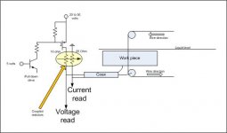
Question. I'm designing a microwire edm system, so need pulses for the spark gap which are 20 to 30 nanoseconds wide, to the tune of 20 to 50 volts. Attached is the rough scheme I'm thinking about. I believe I'll be potting the powerfet, some cap energy storage and the two resistors into an assembly that I put in the liquid just below the wire pulley under the work. The power resistor and the CVR will be my low inductance style, with 20 by 1 ohm resistors in parallel, interleaved through 20 by 200 ohm paralleled array, for net inductance in the dirt. I'm connecting to the work and wire with a very small loop to lower inductance, and I'm keeping all the current path under the liquid surface to take advantage of liquid damping to reduce wire resonances (any mode)
My question is, any suggestions on how to draw a pair of resistors on the schematic to reflect "magnetically interleaved for low inductance" geometry?? Has anybody seen that before?
Also, you circuit guys..I'm using a common base to turn the p fet on, with maybe a 100 ohm resistor to turn it off, and pulling the emitter with a resistor/fet combo such that the transistor never saturates. Any obvious problems or comments would be much appreciated. (edit: other than the wrong polarity fet of course) .. I'm interested in seeing risetimes at the 1 to 2 nanosecond level..
thanks,
jn
ps. eventually, I'd like to go with a double pulse scheme, with opposite voltages to counteract electrolysis. But for now, I'm keeping it simple.
Maybe -- I see both models being used is the point.
here is another view of where the 'skin' effect is happening:
View attachment 429589
THx-RNMarsh
looks like one of the depictions in tom van doren's work..
Question. I'm designing a microwire edm system, so need pulses for the spark gap which are 20 to 30 nanoseconds wide, to the tune of 20 to 50 volts. Attached is the rough scheme I'm thinking about. I believe I'll be potting the powerfet, some cap energy storage and the two resistors into an assembly that I put in the liquid just below the wire pulley under the work. The power resistor and the CVR will be my low inductance style, with 20 by 1 ohm resistors in parallel, interleaved through 20 by 200 ohm paralleled array, for net inductance in the dirt. I'm connecting to the work and wire with a very small loop to lower inductance, and I'm keeping all the current path under the liquid surface to take advantage of liquid damping to reduce wire resonances (any mode)
My question is, any suggestions on how to draw a pair of resistors on the schematic to reflect "magnetically interleaved for low inductance" geometry?? Has anybody seen that before?
Also, you circuit guys..I'm using a common base to turn the p fet on, with maybe a 100 ohm resistor to turn it off, and pulling the emitter with a resistor/fet combo such that the transistor never saturates. Any obvious problems or comments would be much appreciated. (edit: other than the wrong polarity fet of course)
.. I'm interested in seeing risetimes at the 1 to 2 nanosecond level..thanks,
jn
ps. eventually, I'd like to go with a double pulse scheme, with opposite voltages to counteract electrolysis. But for now, I'm keeping it simple.
Attachments
Last edited:
looks like one of the depictions in tom van doren's work..
Question. I'm designing a microwire edm system, so need pulses for the spark gap which are 20 to 30 nanoseconds wide, to the tune of 20 to 50 volts. Attached is the rough scheme I'm thinking about. I believe I'll be potting the powerfet, some cap energy storage and the two resistors into an assembly that I put in the liquid just below the wire pulley under the work. The power resistor and the CVR will be my low inductance style, with 20 by 1 ohm resistors in parallel, interleaved through 20 by 200 ohm paralleled array, for net inductance in the dirt. I'm connecting to the work and wire with a very small loop to lower inductance, and I'm keeping all the current path under the liquid surface to take advantage of liquid damping to reduce wire resonances (any mode)
My question is, any suggestions on how to draw a pair of resistors on the schematic to reflect "magnetically interleaved for low inductance" geometry?? Has anybody seen that before?
Also, you circuit guys..I'm using a common base to turn the p fet on, with maybe a 100 ohm resistor to turn it off, and pulling the emitter with a resistor/fet combo such that the transistor never saturates. Any obvious problems or comments would be much appreciated. (edit: other than the wrong polarity fet of course)
thanks,
jn
ps. eventually, I'd like to go with a double pulse scheme, with opposite voltages to counteract electrolysis. But for now, I'm keeping it simple.
An ultrasonic array I helped work on a while ago used logic level fets driven from an FPGA directly with about 2nS rise and fall for 500 Volt pulses, that was confirmed using the spectrum Analyser and a very fast scope to calculate the same risetime using both techniques. so smaller fets driven carefully should give good results. It was all SMD carefully boxe shielded on the PCB to keep stray fields under control.
Also to JCX Large transformers have to have their construction and lead in lead out wires supported carefully so that they will mechanically survive a shorting event. The ones I worked with were 2.4KV in 600 VAC out, 1000 Amps each, and a design target that we accidentally tested was to short out the secondaries, the forces involved get quite big. Those are the forces JN is talking about.
Wrinkle
Interesting. Magnetic lead?
jn
My procedure was simple. First thing each morning make up a test cable, power up the computer when it booted turn on the AP and run the first test. After it completed, torture the wire and run a second test. Got very nice repeatable results each day.
Turns out the computer has a temperature activated fan!
Nice simple recurring error! My bad...
An ultrasonic array I helped work on a while ago used logic level fets driven from an FPGA directly with about 2nS rise and fall for 500 Volt pulses, that was confirmed using the spectrum Analyser and a very fast scope to calculate the same risetime using both techniques. so smaller fets driven carefully should give good results. It was all SMD carefully boxe shielded on the PCB to keep stray fields under control.
Wrinkle
500 volts is way outta my league...
With microwire edm, surface finish and gap kerf are determined by the voltage and how much material is eroded with every spark. I'm trying to get the kerf down to about 1 or 2 mils (.001/.002 inches), so the voltage will be in the 20 volt range with DI water. But yah, smaller fets is the name of the game so I don't have to drive a gate so hard.jn
My procedure was simple. First thing each morning make up a test cable, power up the computer when it booted turn on the AP and run the first test. After it completed, torture the wire and run a second test. Got very nice repeatable results each day.
Turns out the computer has a temperature activated fan!
Nice simple recurring error! My bad...
Very nice catch..
jn
Very nice catch..
jn
No, my bad. Could mean Scott is right, don't know how to live with myself. Guess I gotta ask SY for advice!
jn, sad to see you being so petty about this - isn't a cause for relief if we've identified the difference in assumptions that have been used?
EM is of course one unified phenomena - a understanding since Maxwell
Newton, Hook, Young aren't the 1st names I think of when modeling EM comes to mind
Multiphysics is as Scott said a long established, well understood term in the physical modeling world
changing geometry under EM forces is a recognized possible source of distortions
Capacitor plates squeezing the dielectric - again we have practically unmeasureable distortion in polystyrene caps used in audio
or you can make your dielectric out of soft rubbery plastics and make electrostrictive actuators
Inductor wire motion - I haven't seen any measurements of distortion components separately attributed to coil internal motion - just hand waving, or complaints about audible acoustic output from the parts - potting is often used anyway
but I agree it is in principle possible and stipulate that it involves several steps - electrical forces, mechanical compliance, changing geometry changing electrical properties
"motor effect" forces between conductors in a cable - the observation of welding cable jumping with 100s A transients are hoary standbys in the audiophile cable debates
I, and apparently many others, class all of these as higher complexity, "multiphysics" problems - involving EM forces causing physical deflections, modifying geometry - which does "modulate" the electrical models
Last edited:
No, my bad. Could mean Scott is right, don't know how to live with myself. Guess I gotta ask SY for advice!
No problem at all, see how subtle the confusers can be.
Why the diversionary schtick??jn, sad to see you being so petty about this
An intellectual discussion should not tolerate diversion nor misrepresentation.
I've been quite clear and very clean with respect to what I've said.
That said, this of yours: (bolded/italicized)
changing geometry under EM forces is a recognized possible source of distortions
Capacitor plates squeezing the dielectric - again we have practically unmeasureable distortion in polystyrene caps used in audio
or you can make your dielectric out of soft rubbery plastics and make electrostrictive actuators
Inductor wire motion - I haven't seen any measurements of distortion components separately attributed to coil internal motion - just hand waving, or complaints about audible acoustic output from the parts - potting is often used anyway
but I agree it is in principle possible and stipulate that it involves several steps - electrical forces, mechanical compliance, changing geometry changing electrical properties
"motor effect" forces between conductors in a cable - the observation of welding cable jumping with 100s A transients are hoary standbys in the audiophile cable debates
Has NOTHING to do with what I've been talking about.
Please ask questions if you are not clear of content or intent.
I, and apparently many others, class all of these as higher complexity, "multiphysics" problems - involving EM forces causing physical deflections, modifying geometry - which does "modulate" the electrical models
What you are classing as "multiphysics", is bog standard work stuff. What Scott mentioned, the thermal/electrical stuff on IC dies, that's wicked stuff..
jn
my question is then what are your talking about? - because not just myself as a undergrad degreed engineer with limited EM understanding - but some PhD physicists here don't seem to understand what you're trying to say
show a calculation - point to a text, a paper
show a calculation - point to a text, a paper
Last edited:
No problem at all, see how subtle the confusers can be.
Huh? What? Boy am I confused.
That'll teach me to respond within the 30 minute timeframe of your posts..
And what way is that? You still misrepresent my arguments in order to shoot them down, basic internet strawman arguments.
You need to understand proximity effects, you really are flailing about. Non linear effects due to proximity/current/high db/dt occurs far deeper than simple skinning. Simple skinning doesn't move the centroid. Proximity does.
Not so strangely, I've seen many people try to build and shoot down strawman arguments as you are doing here.
jn
I would be very surprised to meet a real physicist who misunderstands skin effect in the way you do
And what way is that? You still misrepresent my arguments in order to shoot them down, basic internet strawman arguments.
Really? I didn't say that.. Again with the misrepresentations, the strawman arguments.If skin effect really does depend on rate of change then it would disappear twice in each cycle - we would momentarily have DC current distribution and so DC resistance.
You need to understand proximity effects, you really are flailing about. Non linear effects due to proximity/current/high db/dt occurs far deeper than simple skinning. Simple skinning doesn't move the centroid. Proximity does.
Why do you keep talking about rf guys? Do they make 60 hz generators also??Don't you think the RF guys would notice if all their wires, inductors and transmission lines started generating significant amounts of second harmonic?
It would have to be a major feature of all RF textbooks. Strangely, I have never seen it - I have several RF textbooks at various levels from technician/hobbyist up to graduate.
Not so strangely, I've seen many people try to build and shoot down strawman arguments as you are doing here.
jn
my question is then what are your talking about? - because not just myself as a undergrad degreed engineer with limited EM understanding - but some PhD physicists here don't seem to understand what you're try to say
That's what happens when the gut reaction (not you, btw) is to not understand what somebody is saying yet respond anyway.
A simple case:
When an air core inductor of large awg (#10awg) is swept from DC to a high frequency, the current will first be uniform, and then as frequency goes up, it will begin to confine itself in the wire to the place of lowest inductance. The actual cross section of copper used goes down, and the resistive heating goes up.
This is not pure skinning, albeit the mechanism is similar, that of exclusion (lenz).
It is enhanced by the number of turns.
It produces an asymmetrical current distribution which lowers the overall inductance.
The resistance of the conductor is dependent on the slew rate of the current at the frequencies of interest in this case. The skin depth of copper at 60 hz is about 2 inches, waaaay deeper than this conductor's diameter. When a conductor is being forced into proximity heating at a frequency so low that it's skin depth is far larger than the conductor diameter, the centroid can move as a consequence of excitation slew..
At 20 KHz, skinning would have the center current density at about 70% of the surface (bessels), yet a 5 mH air core inductor of #10awg will have in excess of a kilo-ohm effective overall resistance due to proximity effect, about three plus orders of magnitude less copper area than the cross section. And the conductor size does not prevent centroid movement during this sine excitation. Cylindrical conductors will maintain the exact centroid for single wires and coax.
As I stated a few hundred posts ago, I do not believe skinning at audio levels, in single conductors, will produce measureable distortions. Yet again and again, that is attributed to me in strawman arguments.
Rf arguments are silly for this example as well, yet I'm sure they will be presented again and again.
edit: The example of the force on the VC of an electrodynamic speaker whose field is sine driven is an example of an entity produced (force) which is not a linear result of the excitation, but rather, the product of the two. That is a physical system which generates a non linear response (force in this case) to stimulus. It was not meant to be extended as a strawman argument into conductor movement as another did, but as an example of nonlinear output.(or better stated, not a filtered output of the stimulus)
jn
Last edited:
500 volts is way outta my league...
jn
my simple point was that if a high voltage, slower fet could manage about 1Kv per nanosecond with just an FPGA driving it then a smaller fet should do it quite easily
my simple point was that if a high voltage, slower fet could manage about 1Kv per nanosecond with just an FPGA driving it then a smaller fet should do it quite easily
Got that, thanks. I was just amazed at the voltage and speed. Any idea which fet?
jn
Got that, thanks. I was just amazed at the voltage and speed. Any idea which fet?
jn
Sorry, it was several years ago. I do not remember, but surface mount, logic level 500 Volt fets should narrow it down. The Manufacturers spec gave 5-10nS for risetime, but their fixture didnt address loop area the way it was dealt with in the circuit we had I guess?
My question is, any suggestions on how to draw a pair of resistors on the schematic to reflect "magnetically interleaved for low inductance" geometry?? Has anybody seen that before?
Also, you circuit guys..I'm using a common base to turn the p fet on, with maybe a 100 ohm resistor to turn it off, and pulling the emitter with a resistor/fet combo such that the transistor never saturates. Any obvious problems or comments would be much appreciated. (edit: other than the wrong polarity fet of course)
thanks,
jn
You mean like wire wound resistors do to lower inductance? Cross cancelling fields?
-RM
jn, that's actually something new from you - enough to think about
I do still take a "faith based" approach to the Linearity of EM to get my expectation that even in the heavy wire solenoid that proximity effects modifying internal inductance is going to come out Linear
in my view the heating effect is again a "add on" extra layer of physical modeling - heat capacity, thermal conductivity and temperature coefficient of conductors modifies the EM calcs - but is not "inherent" in them
at least I think I could make baby steps towards estimating magnitudes of the heating effect with FreeField free student edition
but I suspect that the effect is really small - need to find the amplitude of the Cu conductivity varying at the 2nd harmonic of the excitation current caused heating - filtered by the heat capacity, diffusion into the bulk of the wire from the proximity enhanced current density region - just to start
can't I just spec foil, bunch or Litz winding when loudspeaker drivers become linear enough to notice the XO air core inductor "resistance modulation" distortion products?
- Status
- Not open for further replies.
- Home
- Member Areas
- The Lounge
- John Curl's Blowtorch preamplifier part II