This thread is exclusively for feedback about the "pioneer" batch of Korg B1 completion kits and chassis.
We are doing things a little differently this time by soft-launching the first batch of kits to builders most active in the Korg B1 thread. We will gather feedback and make any needed adjustments to the kit, chassis and instructions before opening up a pre-order for the full kit to the public.
There shouldn't be too many issues, but you never know until people starting building.
To be eligible to grab one of these kits previous experience is not required (a wide range of skill levels would be ideal). However as the purpose of the exercise is to gather solid feedback from real builders we do kindly ask that you:
The pioneer batch of chassis and completion kits can be purchased from this store location which is not accessible via the main store navigation:
Korg Nutube B1 – diyAudio Store
Once the final production run has started, this thread will be closed and locked.
We are doing things a little differently this time by soft-launching the first batch of kits to builders most active in the Korg B1 thread. We will gather feedback and make any needed adjustments to the kit, chassis and instructions before opening up a pre-order for the full kit to the public.
There shouldn't be too many issues, but you never know until people starting building.
To be eligible to grab one of these kits previous experience is not required (a wide range of skill levels would be ideal). However as the purpose of the exercise is to gather solid feedback from real builders we do kindly ask that you:
- Either be in the US, or if international choose an express shipping method
- Be ready to start building immediately and give feedback within days (the sooner you give feedback, the sooner we can offer this kit to everyone else)
- Be prepared to resolve any minor problems yourself
The pioneer batch of chassis and completion kits can be purchased from this store location which is not accessible via the main store navigation:
Korg Nutube B1 – diyAudio Store
Once the final production run has started, this thread will be closed and locked.
Last edited:
The SUPER guys here, Jason and 6L6 have asked me to post some notes/observations etc., about this build. (Not sure what if any of this will be relevant to a lot of you since it's clear to me there are some super creative minds on this forum...)
Below is what I sent them as feedback about the build—and a picture of the success!!! Will listen to it today—though not in my main system—soon.
This is from the perspective of someone who’s never done this type of work before, but has some basic skills. I have built 2 ACAs and have gotten into the crazy with prepping my mind and procuring all the components for an F5 build, including Quasimodo, etc. This involved some super critical (and probably ongoing!) help from 6L6 and board member Fidget. So thanks to those guys—
Since I sent this feedback below to dev team last night—I've added a couple of other bits of info since I now have the NuTube B1 powered up...
I'm glad I jumped in on the pre-release since it presented some good challenges and some continued ongoing thought about what was made all without the point by point instructions of a build guide like the ACA.
I like to have to work a bit for the information—it helps me learn, personally—but there’s some basic mechanical stuff that has to be dealt with too—like soldering technique, DMMs and taking measurements, reading electrical layouts and wiring diagrams—that can be challenging in their own right—which is why the ACA is the perfect gateway drug. On my wishlist for the Korg B1 would be a 3rd input—not that I need it right now, nor is there really room in the chassis and it would mean a dial and different silkscreen, etc.…but…DIY future build maybe.
(See page 127 of the original B1 Korg thread!! — guess I was too excited to read EVERYTHING.)
I made some updates in bold to the original text.
------------------------------------------------------------- //// -------------------------
Board:
Wiring:
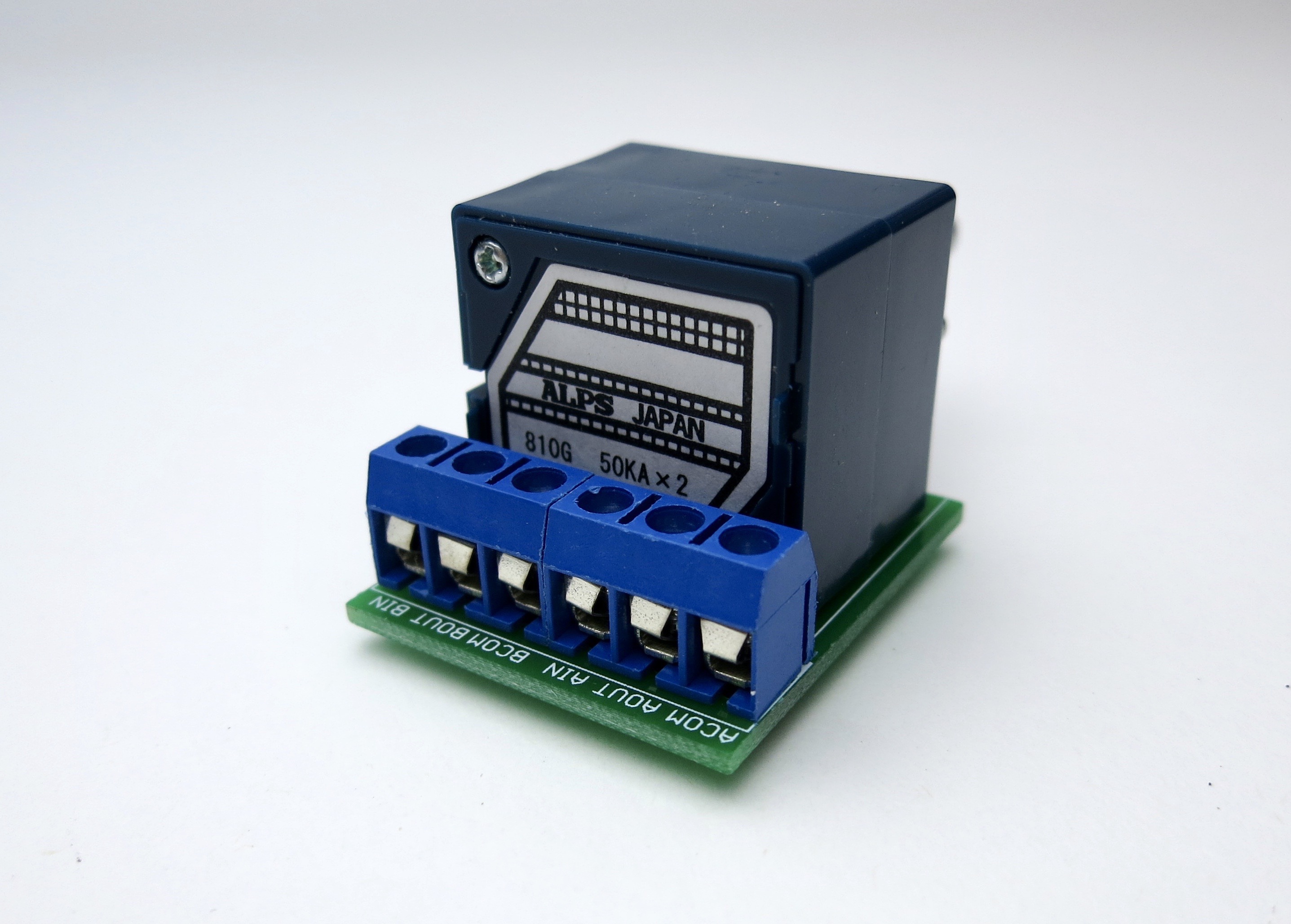
I think I can figure out most of the final connections to the board. Seems pretty straight forward with a little help from a couple of Jim’s pics that show the ALPS side. From the ALPS I’m not totally sure what defines Left and Right inputs as far as where they connect to the board….Is AOUT Right or Left IN? Maybe it doesn’t matter? After I get it powered and don’t see any orange or red on the Korg I think Nelson's testing procedures are pretty clear in the paper. Is it a thing to add a pin to T7? Or just probe it? The pots are supposed to be zeroed/centered… Not sure I can tell where they are set unless I mess with them. Normal? (Need to find an internal diagram of an ALPS pot and I'm sure that will clarify things for me)—The testing came out perfect across the board—Nelson's instructions on this are very clear in his paper—I settled T7, T8 at 9.5V—I was confused about how the common wires on the input switch related to the ALPs board and the input RCAs—I still don't have this down 100%—likely it's a visual thing and when I build another one !!!!!!! I'll roll my own wiring color scheme that fits my particular brain. Jim got me out of that jam for this one. Pretty sure everyone up here owes that guy something! Group gift? Just sayin.
Another somewhat random thing. Using the Cardas solder… how important is it to clean a circuit board of flux? Is it critical long term? Is Laquer thinner ideal? Does alcohol work? You would want to be very selective with how you use the chemicals? Q-tips?
When do we get to try out some Fire-Metall?? Nice ads there in Jim’s images.
I think I’m either going to buy another B1 Korg board and parts kit to build just to frame it to hang on my wall sans chassis, or make a lucite top cover for the chassis. (Need ventilation?) Maybe both!
Lastly, I do think the ACA build guide is a great balance of images and instructional text. The ability to add community comments is amazing and helpful. I do however, as stated earlier, like the “work” I’m having to do to unlock the secrets of the F5. Not sure if that is normal or not… That said… I has to be stated that not having everything spelled out does increase the risk of failure even though it’s less adventurous.
I don’t think I will be able to NOT finish it ASAP tonight… Even though I have a big deadline tomorrow. (This was true. I did finish it.)
Hope this is a little helpful. Keep up the awesome work.
Thanks!!
Below is what I sent them as feedback about the build—and a picture of the success!!! Will listen to it today—though not in my main system—soon.
This is from the perspective of someone who’s never done this type of work before, but has some basic skills. I have built 2 ACAs and have gotten into the crazy with prepping my mind and procuring all the components for an F5 build, including Quasimodo, etc. This involved some super critical (and probably ongoing!) help from 6L6 and board member Fidget. So thanks to those guys—
Since I sent this feedback below to dev team last night—I've added a couple of other bits of info since I now have the NuTube B1 powered up...
I'm glad I jumped in on the pre-release since it presented some good challenges and some continued ongoing thought about what was made all without the point by point instructions of a build guide like the ACA.
I like to have to work a bit for the information—it helps me learn, personally—but there’s some basic mechanical stuff that has to be dealt with too—like soldering technique, DMMs and taking measurements, reading electrical layouts and wiring diagrams—that can be challenging in their own right—which is why the ACA is the perfect gateway drug. On my wishlist for the Korg B1 would be a 3rd input—not that I need it right now, nor is there really room in the chassis and it would mean a dial and different silkscreen, etc.…but…DIY future build maybe.
(See page 127 of the original B1 Korg thread!! — guess I was too excited to read EVERYTHING.)
I made some updates in bold to the original text.
------------------------------------------------------------- //// -------------------------
Board:
- I found it much easier to solder the resistors from the top of the board—then finalize them where needed from the bottom. I used a small conical tip, like what’s in Jim’s pics (or will be when they are live).
- When adding the JFETs I followed Nelson’s recommendation of tacking one pin from the top for neatness and alignment and then finishing them off on the bottom. The multiple QX spots on the board threw me at first until I reread Nelson’s article—it’s quite clear.
- the caps were challenging since it’s hard to judge the right amount of solder, but the Nichicons have a separator on the bottom that looks like it would prevent shorts.
- I wasn’t sure what, if anything, I should be measuring for the device on the power side in the 9.1v spot. What is that guy called? And what does he do exactly? Assuming there isn’t polarity there (There IS! got a little lucky.). I didn’t leave any space under that part… okay? (Yes, I now know what that zener diode is—more research)
- I left space under the power side big resistors. Dunno if that is always a good thing or not. I used one of the nuts off a switch as a temp spacer and soldered them from the top. Worked out great.
Wiring:
- Jim’s images are great as usual—I got a bunch last night around 11pm my time… yea… didn’t go to bed til around 2am…. haha.
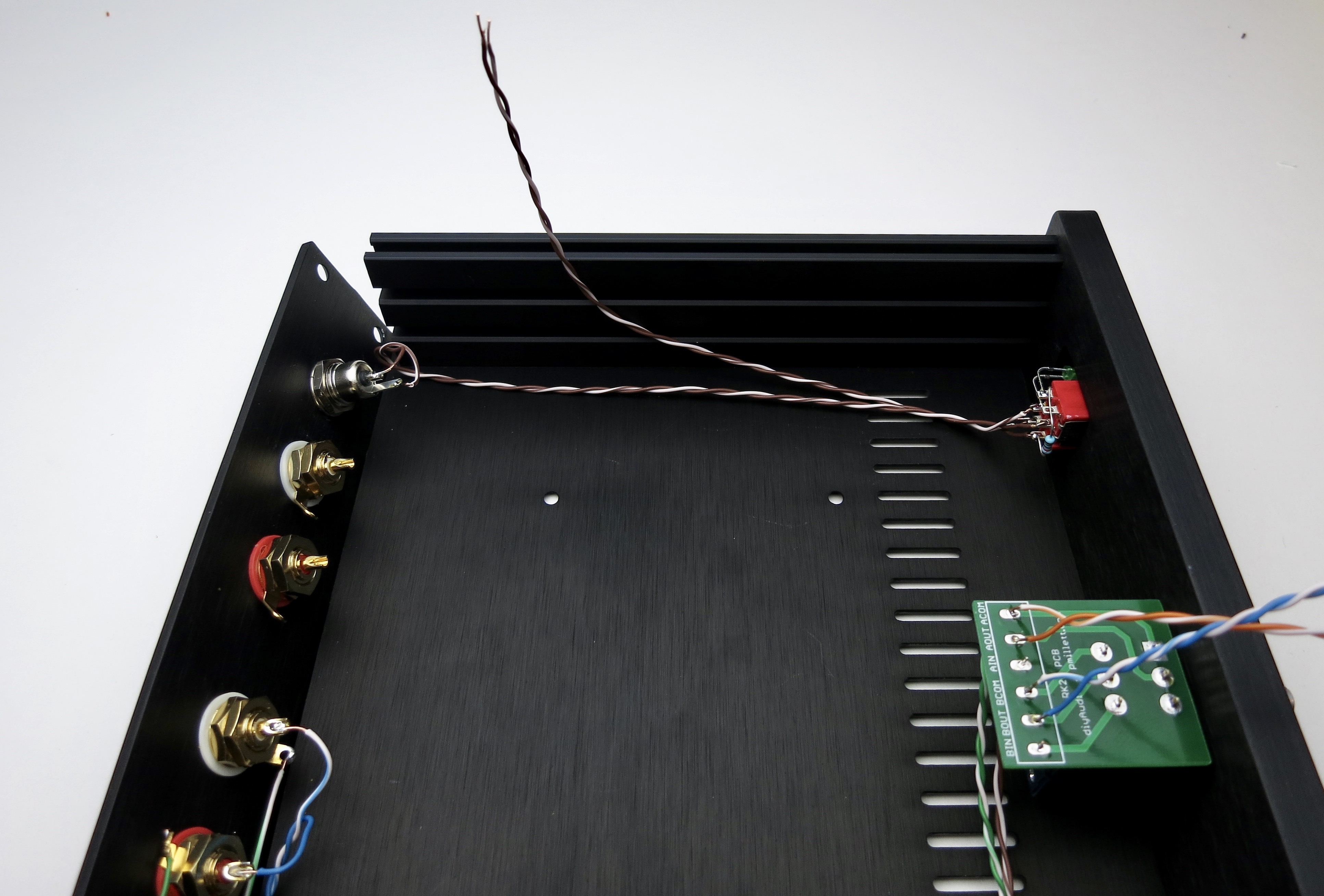
- I was/am confused by the image that shows wiring the power switch and which set of terminals, once soldered, connect to the power socket—Following the double brown/white wires is impossible visually as they leave the switch, in the image. Separating them more, for the image, would be cool to add clarity. That prompted looking for understanding about SPDT (correct?, NO!) switches and then the knowledge that the center terminals are the power. This was further clarified by wiring the input switch to the ALPS.
- Is the wiring shown in the images backwards for inputs? Blue at the top of the toggle is connecting to the "input 2" RCAs at the back. Is “up” on the switch actually connecting internally to the bottom leads? I wired it the way Jim’s images showed.. That seems backwards in my brain. Based on how the power side is wired and my SPDT research, I’m answering my own question—and thinking it’s what I just stated—“Up” toggle activates bottom leads… But, that is super confusing to the visually oriented! Up should correspond with the top leads! I haven’t searched yet for a cutaway of the interior mechanics of a switch like this. But maybe I have this totally wrong and Jim was so excited to make the instructional that he didn’t wire it right? Haha. Didn’t think so. (I've since found an internal wiring diagram of an DTDP switch—makes sense!)
- I had a family request for “not a green LED”, so I put in a white—we shall see if it’s blinding with a 10K. (Yes, pretty retina-searing—I added an additional 15K that I picked up for F5 LED options, and that brought it down to a good level for me considering that you really only get blinded if you look exactly into it—could go higher—another 20K perhaps easily—here's the Digikey PN for the LED I bought: 751-1502-ND)
I haven’t told my wife that the F5 will glow blue internally. - By far, the hardest part of this build for me was working on the LED (kinda like the ACA) (Not true, wiring was harder, but I hadn't done that yet). Not hard, fun really … but I wanted it to have a tad bit of spring and sit in the hole perfectly—and I had gotten it all lined up before realizing how the washers stack up on the inside… It was a blast making it all as neat as possible though. I did have to “guess” about the polarity of the LED. I made the assumption that it mattered, and put the positive leg up (Nobody has told me otherwise, but when I test them with the DMM they only light up in one direction...). Hopefully I don’t hear back that that is backwards. It seemed logical to me, but it was a guess nonetheless.
I think I can figure out most of the final connections to the board. Seems pretty straight forward with a little help from a couple of Jim’s pics that show the ALPS side. From the ALPS I’m not totally sure what defines Left and Right inputs as far as where they connect to the board….Is AOUT Right or Left IN? Maybe it doesn’t matter? After I get it powered and don’t see any orange or red on the Korg I think Nelson's testing procedures are pretty clear in the paper. Is it a thing to add a pin to T7? Or just probe it? The pots are supposed to be zeroed/centered… Not sure I can tell where they are set unless I mess with them. Normal? (Need to find an internal diagram of an ALPS pot and I'm sure that will clarify things for me)—The testing came out perfect across the board—Nelson's instructions on this are very clear in his paper—I settled T7, T8 at 9.5V—I was confused about how the common wires on the input switch related to the ALPs board and the input RCAs—I still don't have this down 100%—likely it's a visual thing and when I build another one !!!!!!! I'll roll my own wiring color scheme that fits my particular brain. Jim got me out of that jam for this one. Pretty sure everyone up here owes that guy something! Group gift? Just sayin.
Another somewhat random thing. Using the Cardas solder… how important is it to clean a circuit board of flux? Is it critical long term? Is Laquer thinner ideal? Does alcohol work? You would want to be very selective with how you use the chemicals? Q-tips?
When do we get to try out some Fire-Metall?? Nice ads there in Jim’s images.
I think I’m either going to buy another B1 Korg board and parts kit to build just to frame it to hang on my wall sans chassis, or make a lucite top cover for the chassis. (Need ventilation?) Maybe both!
Lastly, I do think the ACA build guide is a great balance of images and instructional text. The ability to add community comments is amazing and helpful. I do however, as stated earlier, like the “work” I’m having to do to unlock the secrets of the F5. Not sure if that is normal or not… That said… I has to be stated that not having everything spelled out does increase the risk of failure even though it’s less adventurous.
I don’t think I will be able to NOT finish it ASAP tonight… Even though I have a big deadline tomorrow. (This was true. I did finish it.)
Hope this is a little helpful. Keep up the awesome work.
Thanks!!
Attachments
Last edited by a moderator:
Thanks for such great feedback Patrick!
Someone just relayed to me the following "two solvent cleaning method" cleaning method which he found resulted in an amazing finish on another project...
If you try this please see if you can do a before and after photo?
Very excited about that product from a fellow diyAudio member. Feedback has been great. Sounds like it will be a few months yet though.
Another somewhat random thing. Using the Cardas solder… how important is it to clean a circuit board of flux? Is it critical long term? Is Laquer thinner ideal? Does alcohol work? You would want to be very selective with how you use the chemicals? Q-tips?
Someone just relayed to me the following "two solvent cleaning method" cleaning method which he found resulted in an amazing finish on another project...
Two-solvent cleaning method is just a toothbrush + 99% isopropyl alcohol for passes 1 & 2, followed by a different toothbrush + hand soap + lukewarm water for passes 3 & 4, followed again by toothbrush 1 and 99% isopropyl alcohol for passes 5 & 6. Alcohol dissolves most of the flux. The soap and water dissolves those flux deposits which alcohol does not. And the second application of alcohol, acts as a solvent to lift and whisk away the soap and water. Sounds batty, works great.
If you try this please see if you can do a before and after photo?
When do we get to try out some Fire-Metall?? Nice ads there in Jim’s images.
Very excited about that product from a fellow diyAudio member. Feedback has been great. Sounds like it will be a few months yet though.
I received the kit a few days ago and built it over the past couple of nights. Everything in the kit was complete, and the build was the easiest of any of the other Pass designs I've built (ACA, F6, M2 and Aleph J). Well, one difficult part was finding the chassis screws in the carpet when I dropped them.
I used double sided foam tape between the nutube and the board and have no issues with microphonics when I rap on the chassis.
I have very little constructive feedback on the kit because everything went very well. However, when instructions are available, you might consider:
- specifying which JFets are included in the kit so the builder can easily identify which area to populate on the board. Even with a magnifying glass, I had a tough time reading the printing on the JFets.
- specifying the the resistance of the bias resistors, so the builder can verify they are correct.
It's a great little kit! I am really looking forward to the remote volume control option (hint hint).
I actually built my B1 with Korg NuTube a few weeks ago and I brought it with me on a recent business trip to the San Francisco Bay Area and reunited with a few audio friends.
Building the Kit
I first populated the PCB as instructed by Nelson Pass. Since the bags of parts were not labeled, it took me a while to identify everything including measuring the nice Vishay-Dale RN55 resistors and the larger power supply filter resistors.

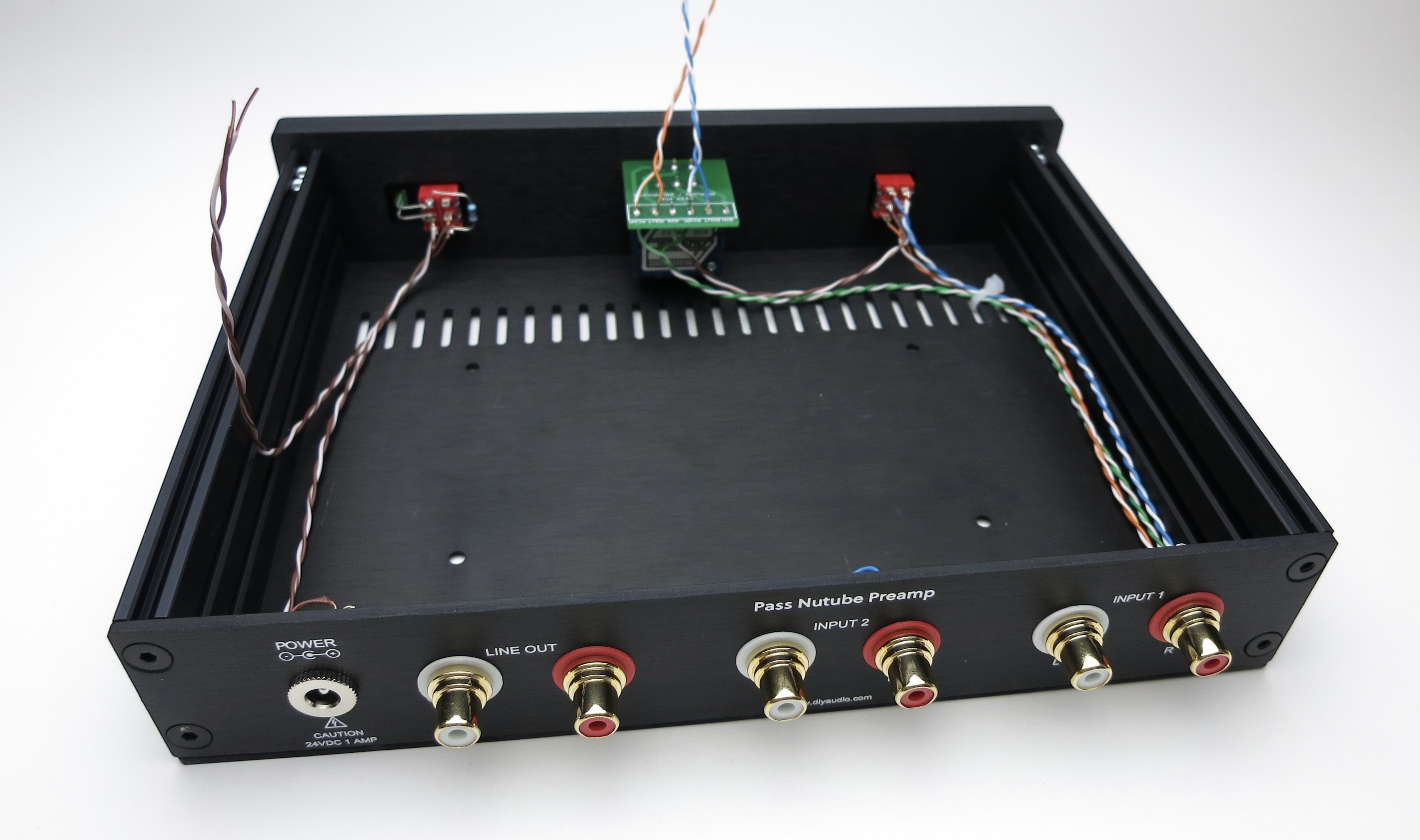
Next, I soldered the volume pot, the source input switch, power supply connector, power switch, LED, resistor and then RCA connectors. After that, I assembled the chassis and installed the RCA connectors. I soldered the signal input wiring and DC power wiring afterward. For my build, I used Duelund DCA20GA Cotton-insulated, Silver-plated Copper wire for the signal hook-ups, and Kimber Kable TCSS Teflon-insulated AWG 19 stranded Copper wire for the DC power connections.
Thanks to Jim for advising me to tie the respective Left and Right channel input grounds together before I wired up the connections.

I plugged in the power supply and went through the test measurements and adjusted the bias pots as instructed. I ended setting up the voltages at T7 and T8 at 10.0 VDC. Unfortunately, I do not have a distortion analyzer, but relied on what I liked best.

Everything worked like a charm. Jim's photos were very helpful in insuring that my soldered wire connections were correct.
The Sound
Initially, I had some problems with microphony at loud volumes, but placing the preamp on some vibration damping feet and assembling the top cover onto the chassis took care of it.
I traveled to the San Francisco Bay Area and I shipped my preamp to one of my audio friends to audition it with his system. My friend, who is a an avid record collector and audiophile, remarked how natural the preamp sounded with his Conrad-Johnson MV75-A1 tube power amp and KEF Reference 101 monitors. I have to admit the sound coming through his system was tonally rich and dynamic. It got so good, my friend brought out his 6-eye Columbia pressing of Miles Davis' "Kind of Blue" and we marveled at the natural presentation in the midrange where the horns really shine. It was truly remarkable.
Next, I visited a friend whose system consists of a Texas Instruments TPA-3255EVM Class D power amplifier and Klipsch Forte II floor standing speakers. My friend is a musician and has very critical listening skills. He remarked at the smoothness and higher frequency detail along with the outstanding separation of musicians in the recordings we listened to. I was impressed with the very warm, and dynamic presentation. All of this really allowed us to hear the interplay between musicians. In this system, we really noted the timing, attack and decay of the various instruments, especially with percussion instruments.
In both systems, I noted how the bass definition had improved. I also heard a very large and deep soundstage with imaging that created a very realistic presentation of the music. In the second system, we experienced problems with microphony, so I intend to implement some additional vibration damping to the PCB mounts and chassis.
Both of my friends have commented how professional the preamp looks. It certainly is a nice, compact package. Overall, I am very pleased with the purchase. Hopefully, this feedback will help others.
Building the Kit
I first populated the PCB as instructed by Nelson Pass. Since the bags of parts were not labeled, it took me a while to identify everything including measuring the nice Vishay-Dale RN55 resistors and the larger power supply filter resistors.
Next, I soldered the volume pot, the source input switch, power supply connector, power switch, LED, resistor and then RCA connectors. After that, I assembled the chassis and installed the RCA connectors. I soldered the signal input wiring and DC power wiring afterward. For my build, I used Duelund DCA20GA Cotton-insulated, Silver-plated Copper wire for the signal hook-ups, and Kimber Kable TCSS Teflon-insulated AWG 19 stranded Copper wire for the DC power connections.
Thanks to Jim for advising me to tie the respective Left and Right channel input grounds together before I wired up the connections.
I plugged in the power supply and went through the test measurements and adjusted the bias pots as instructed. I ended setting up the voltages at T7 and T8 at 10.0 VDC. Unfortunately, I do not have a distortion analyzer, but relied on what I liked best.
Everything worked like a charm. Jim's photos were very helpful in insuring that my soldered wire connections were correct.
The Sound
Initially, I had some problems with microphony at loud volumes, but placing the preamp on some vibration damping feet and assembling the top cover onto the chassis took care of it.
I traveled to the San Francisco Bay Area and I shipped my preamp to one of my audio friends to audition it with his system. My friend, who is a an avid record collector and audiophile, remarked how natural the preamp sounded with his Conrad-Johnson MV75-A1 tube power amp and KEF Reference 101 monitors. I have to admit the sound coming through his system was tonally rich and dynamic. It got so good, my friend brought out his 6-eye Columbia pressing of Miles Davis' "Kind of Blue" and we marveled at the natural presentation in the midrange where the horns really shine. It was truly remarkable.
Next, I visited a friend whose system consists of a Texas Instruments TPA-3255EVM Class D power amplifier and Klipsch Forte II floor standing speakers. My friend is a musician and has very critical listening skills. He remarked at the smoothness and higher frequency detail along with the outstanding separation of musicians in the recordings we listened to. I was impressed with the very warm, and dynamic presentation. All of this really allowed us to hear the interplay between musicians. In this system, we really noted the timing, attack and decay of the various instruments, especially with percussion instruments.
In both systems, I noted how the bass definition had improved. I also heard a very large and deep soundstage with imaging that created a very realistic presentation of the music. In the second system, we experienced problems with microphony, so I intend to implement some additional vibration damping to the PCB mounts and chassis.
Both of my friends have commented how professional the preamp looks. It certainly is a nice, compact package. Overall, I am very pleased with the purchase. Hopefully, this feedback will help others.
Last edited:
Both of my friends have commented how professional the preamp looks. It certainly is a nice, compact package. Overall, I am very pleased with the purchase. Hopefully, this feedback will help others.
Super professional I agree. I would consider sourcing a different stick-on foot/bumper. Perhaps something that's at least 1/4" tall (Digi-Key: SJ5748-0-ND)? It's a tad taller. No idea if it's wise or not to put this on top of 2 stacked ACAs that are running a normal temp of around 120F but the feet that ship with the kit don't clear the face of those amps...
Hi all,
I got the email about the pioneer kit availability and pounced on it. It arrived today and I opened it all up and looked at the board, sorted parts, measured resistors, etc. I also reviewed NP's DIY Nutube Preamp article, and that's where I got nervous. I have built a number of kits over the years (starting with a Dynaco FM-5 in about 1978!), but my limited understanding of DIY electronics is more tube and point-to-point than solid state and PCB. Thus the talk about the Jfets in the article was troubling.
Can someone talk me through the two different Jfets, the resistors and the appropriate pads on the PCB?
Thanks,
Pete
Hi Pete,
The jfets in the Q1 bag will go into the board areas labeled JQ1. The jfets in the Q2 bag will go into the board areas labeled Q2 which are just to the right of each JQ1. Dont use the Q2 positions next to the KQ1 positions. They will remain unpopulated. The board has a little diagram on each jfet area to help you position the jfets correctly.
There are 4 blue colored resistors that are in a bag separate from all the other resistors. They will go into the board areas labeled R1.
I hope this helps.
Alan
Hi Alan,
Thank you - that's exactly what I needed! Leave the KQ1 and 2 slots empty, and the flat part of the Jfet goes with the flat part of the diagram on the board. Got it!
While I've got you - a few more questions:
What's the correct order of washers (with a little tab), lock washers and nuts on the switches? And the RCA jacks, while we're at it.
What's the resistor in the bag with the little pots, the led and the zener?
And how is the led mounted?
Minor victory - I figured out how the cabinet goes together!
Thanks again (and thanks in advance for the follow-up questions),
Pete
Last edited:
Ignorance is my middle name, but somehow I managed to build a bunch of great sounding audio designs without accident. I credit 6L6 as the enabler with his fantastic guides. But alas, they are a gateway drug.
it looks like it will help me avoid the embarrassment of acknowledging my ignorance publicly.
Hi everyone,
This is my first post here -- I feel that being a lucky possessor of one of the kits from the “pioneer” batch I owe some feedback to the community, although I don’t have that much to add -- my experience happened to be pretty smooth and consistent with what has already been mentioned, especially in the wonderful write-up by pfarrell.
TL/DR -- everything was straightforward and the amp works well. Long version, some pics and measurements below.
I’ve done a few builds before (ACA, Starving Student and a couple of other small projects), but that’s about all experience with audio electronics that I’ve ever had.
First of all, thanks a lot to Nelson, Jason, 6L6 and everyone else who made this kit possible -- building it and listening to the preamp coupled with ACA was nothing but a pure joy.
I’ve only read Nelson’s original article before proceeding to stuff and solder the PCB and that proved to be enough. I’ve also used the schematics printout that came with the kit to cross-check, and that brought a bit of surprise, as it is apparently “v0” of the circuit and shows the resistor values in the output voltage divider that are different from the ones on the silkscreen (and the actual parts in the kit). I’ve also had to search a bit for the zener diode (packaged separately) and was momentarily puzzled by the number of JFET footprints on the PCB being twice the number of JFETs, so I had to come back to the article and read about which ones to use.
Building the chassis was also a no-brainer, but when it came to wiring, I felt like I needed some guidance -- there aren’t too many ways to wire the power or signal, but I wanted to make sure the ground topology is sensible, so I had to dig through the thread a bit before I found photos of the build by 6L6. Having an example of how to mount LED on the power switch was also very helpful!
Here are some notes on switches and wiring that basically describe what I’ve seen there -- for those who prefer written instructions:
Here are some pics of my build, although they’re nowhere as neat as others.


I’ve also done some distortion measurements while playing with the bias (after all, wasn’t that the entire point of the project?), using RAW + Focusrite Scarlett 2i2 + Pete Millet ATEST interface. Here are a couple of graphs and a summary for all the voltages that I tried, all for one channel (I found that there is around 0.2% discrepancy between THD values of two channels at one specific bias voltage when I tried measuring second channel). All measurements are done at 1V RMS output, 1KHz.


Once again, thanks for all who worked on making this kit available, bulding and playing with it was a lot of fun and it sounds good!
This is my first post here -- I feel that being a lucky possessor of one of the kits from the “pioneer” batch I owe some feedback to the community, although I don’t have that much to add -- my experience happened to be pretty smooth and consistent with what has already been mentioned, especially in the wonderful write-up by pfarrell.
TL/DR -- everything was straightforward and the amp works well. Long version, some pics and measurements below.
I’ve done a few builds before (ACA, Starving Student and a couple of other small projects), but that’s about all experience with audio electronics that I’ve ever had.
First of all, thanks a lot to Nelson, Jason, 6L6 and everyone else who made this kit possible -- building it and listening to the preamp coupled with ACA was nothing but a pure joy.
I’ve only read Nelson’s original article before proceeding to stuff and solder the PCB and that proved to be enough. I’ve also used the schematics printout that came with the kit to cross-check, and that brought a bit of surprise, as it is apparently “v0” of the circuit and shows the resistor values in the output voltage divider that are different from the ones on the silkscreen (and the actual parts in the kit). I’ve also had to search a bit for the zener diode (packaged separately) and was momentarily puzzled by the number of JFET footprints on the PCB being twice the number of JFETs, so I had to come back to the article and read about which ones to use.
Building the chassis was also a no-brainer, but when it came to wiring, I felt like I needed some guidance -- there aren’t too many ways to wire the power or signal, but I wanted to make sure the ground topology is sensible, so I had to dig through the thread a bit before I found photos of the build by 6L6. Having an example of how to mount LED on the power switch was also very helpful!
Here are some notes on switches and wiring that basically describe what I’ve seen there -- for those who prefer written instructions:
- Remember that these DPDT switches connect the middle pair of the contacts to the pair opposite to the position of the toggle (so if the toggle is “UP”, it’s the bottom pair of contacts will be connected).
- You want the incoming pair of wires from the power socket to go to the bottom contacts of the switch; the below also presumes ‘+’ is wired to the (outer) side where LED is and ‘-’ is on the (inner) side closer to the volume control.
- Bend the leads of the LED at right angle so that the distance from the lens of the LED to the bend matches the depth of the switch body. Observe the direction of the bend, the anode (longer lead) should be at the middle switch contact when mounted, and the cathode should be at the top (presuming the polarity mentioned above). Solder LED to approximately match the distance from switch to the LED hole, the cut the leads.
- At the input terminals, connect the ground tips of ground rings of both LEFT posts using a stripped wire, then connect the tips of both ground rings of RIGHT posts. It helps if the tips of left posts are facing down while the right posts are facing up (or vice-versa).
- Use one twisted pair to connect left and right of first channel to the bottom terminals of the switch, another one to connect the second channel to the top pair of the switch. Color coding is your friend, I keep all LEFT wires white.
- Use third pair to route the ground directly to the COMMON pad of the volume pot’s breakout PCB, but do not solder yet, as you’ll want the ground from pot to the input on the PCB to be mounted there as well.
- Route another pair from the middle terminals of the channel selector switch to the input pads of the volume pot PCB, and finally route two pairs from out and common to left and right on the amp PCB.
Here are some pics of my build, although they’re nowhere as neat as others.
I’ve also done some distortion measurements while playing with the bias (after all, wasn’t that the entire point of the project?), using RAW + Focusrite Scarlett 2i2 + Pete Millet ATEST interface. Here are a couple of graphs and a summary for all the voltages that I tried, all for one channel (I found that there is around 0.2% discrepancy between THD values of two channels at one specific bias voltage when I tried measuring second channel). All measurements are done at 1V RMS output, 1KHz.
Code:
[FONT="Courier New"]
T8 Voltage   % 2nd   % 3rd  % THD
 9.50        1.18    0.14   1.19
10.00        0.92    0.08   0.93
10.50        0.72    0.10   0.73
11.00        0.40    0.19   0.44
11.50        0.11    0.29   0.31
12.00        0.68    0.28   0.74
12.50        1.20    0.18   1.21[/FONT]
Once again, thanks for all who worked on making this kit available, bulding and playing with it was a lot of fun and it sounds good!
Last edited:
Great feedback everybody! I'm very glad its working out well for all involved.
Correct, as of this time the guide is not complete, but most of the photography is, and Ive taken into account things you have said as I finish that up.
The best news is that yes, we've got all the pieces and its all going together smoothly, again, thank you for giving it a try.
There will be drawings for wiring connections and the like in the guide, much like the in the ACA guide.
For those of you who are inclined to experiment with things, I'd love to see any/all experiments, solutions, trials, guesses, etc... to PCB and/or NuTube mounting to see if anything can be done to help tame the microphony. O-rings? Blu-Tac? Soft standoffs instead of metal? Maybe mounting it with foam tape? I don't know, but I'm sure the community can come up with a few things that can help!!
I am going to try a few things to tame the occasional flare-up of microphony:
I am also considering replacing some of the input caps with film caps as some have done; however, replacing the output electrolytic caps with film caps might be limited by the internal space in the chassis.
I just wonder whether changing the volume pot and input caps will really make a significant improvement over what I have now, because I really love what I have now with the exception to the occasional microphony. I need to complete the set up of my lab in my relatively new home so I can measure noise and distortion for before and after each tweak.
For now, I can say that this is one “steal” of a preamp in stock form. One of my buddies in California asked to borrow it for a couple weeks as he is very impressed with the B1K and he will probably purchase the kit himself to build.
- Vibration-isolating standoffs
- Vibration-isolating grommets or o-rings
- Vibration/noise damping sheets on the chassis
- Either hot melt adhesive or Silicone sealant or Silicone sheet under the Korg NuTube triode
I am also considering replacing some of the input caps with film caps as some have done; however, replacing the output electrolytic caps with film caps might be limited by the internal space in the chassis.
I just wonder whether changing the volume pot and input caps will really make a significant improvement over what I have now, because I really love what I have now with the exception to the occasional microphony. I need to complete the set up of my lab in my relatively new home so I can measure noise and distortion for before and after each tweak.
For now, I can say that this is one “steal” of a preamp in stock form. One of my buddies in California asked to borrow it for a couple weeks as he is very impressed with the B1K and he will probably purchase the kit himself to build.
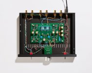
I noticed the pictures show a screw terminator block on the volume daughter board:
Daughter board
There isn't one in my kit, and the first few photos of all the parts don't show one, either.
I don't mind the point to point, but I spent a few minutes rummaging through my packaging to make sure it wasn't missing.
Using these images:
Photo 1Photo 2
I cannot tell if the middle or the bottom twisted pair goes to the power connector. My guess is middle? Or maybe it doesn't actually matter?
Middle connectors go to the power. YES it matters! The center is the common, top and bottom leads are switched. Up on the switch connects the bottom, down on the switch connects the top. (I just learned all of this as well—Look up a wiring diagram of a DPDT switch, it will add clarity.) Way FUN!!
I noticed the pictures show a screw terminator block on the volume daughter board:
Daughter board
There isn't one in my kit, and the first few photos of all the parts don't show one, either.
I don't mind the point to point, but I spent a few minutes rummaging through my packaging to make sure it wasn't missing.
I suspect that 6L6 was presenting some options (don't think the kit includes the blocks—mine didn't...but maybe the "official" kits will? That would be cool—I needed a big fat assist on wiring up the volume.. that type of block would have meant no desoldering—get some solder wick.)... You "could" use a euroblock terminal... I might next time in this scenario since there's all this chit chat about attenuators (potentiometers? note to self—look here more) in the other B1K thread. (That I don't really have a frame of reference for...but makes for interesting reading...)
Although the Amp sounds excellent as-is, I am curious about replacing the Alps RK-27 volume pot with something like a TKD volume pot. I have no bias against the Alps volume pot since that is the stock volume pot in my Audio Research LS7 tube line stage, and I enjoy this as my reference preamp.
I'm always amazed when people (not just you) talk about changing the RK27 for something different... because the assumption is that the RK27 isn't a good pot because it's what is included. Well, those are the single most expensive item in the kit, and quite a bit of discussion was had over including one of that quality and cost when there are solutions that are quite a bit cheaper that would still work superbly. In a retail audio device the use of that pot would easily add $80-100 to the retail price of the preamp like your LS7.
I'm a great fan of the Alps for a few reasons, 1) they track very nicely at low volume (this has a lot to do with physical diameter as well as manufacturing tolerances), 2) the have a great feel, and don't for a second think that isn't important, and 3) they sound fantastic. Sure, there's always somebody who thinks that you are crazy for whatever choices you make, but in this situation more money gains you minuscule improvements.
I have a number of projects with TKD pots and I have to say that they are unquestionably excellent. The question is this - are they 8x the performance? They are 8x the price, so is it fair to expect it being massive amounts better? I can't answer that for you, but then again price/performance in this hobby is not linear at all, and you are so incredibly ahead of that curve by building DIY that nobody would blink if you changed out a fantastic pot for a slightly better one.
I suspect that 6L6 was presenting some options (don't think the kit includes the blocks—mine didn't...but maybe the "official" kits will?
That was the point of the photo - the blocks fit. Use them if you want.

Middle connectors go to the power. YES it matters! The center is the common, top and bottom leads are switched. Up on the switch connects the bottom, down on the switch connects the top. (I just learned all of this as well—Look up a wiring diagram of a DPDT switch, it will add clarity.) Way FUN!!
So when the switch is on the OFF position, the top connectors will actually be powered? I don't think you want this, I'd rather make the bottom connectors go to the socket power and the middle pair go the board, so that in the off position the top pair is actually off.
- Status
- This old topic is closed. If you want to reopen this topic, contact a moderator using the "Report Post" button.
- Home
- The diyAudio Store
- Korg B1 completion kit pioneer batch feedback