Microphonic tube
I just finished building the kit this morning and after passing the smoke test I put the board in the chassis and plugged in my sennheiser 595s. The volume was all the way down to start. The first thing I noticed was a lot of noise on the right channel when I touched the volume knob. Even a light touch caused a lot noise. The noise level was independent of the volume position.
I’m running the tubes with the plate resistor load because I swapped out the blue LEDs for amber ones. I also replaced the resistors with Dale 1% RN55/RN60s, I use the same values and verified each with my DMM. There is no noise unless I touch the chassis or anything near the chassis, it seems clearly to be a microphonic tube. Would I be able to get a replacement tube?
Thanks,
Olen
Does the vol. pot has good electrical contact with front panel?
My front panel was black anodized inside the cut out for vol. knob. So I had to sand the "hole" to get good electrical contact to vol. pot. I think this is the only place where PCB gets its ground contact to chassis. This could remove the vol. knob noise.
My front panel was black anodized inside the cut out for vol. knob. So I had to sand the "hole" to get good electrical contact to vol. pot. I think this is the only place where PCB gets its ground contact to chassis. This could remove the vol. knob noise.
Ok.....have you tried to switch tubes (same tubes but L=R and R=L) to see if the "error" follows the tube?
I think it would be good not to have the chassis electrical floating. It may not solve the current problem you have but may reduce noise. It is a shame that the cut outs is not without the anodization like it seems some of the first production chassis was.
I think it would be good not to have the chassis electrical floating. It may not solve the current problem you have but may reduce noise. It is a shame that the cut outs is not without the anodization like it seems some of the first production chassis was.
I just finished building the kit this morning and after passing the smoke test I put the board in the chassis and plugged in my sennheiser 595s. The volume was all the way down to start. The first thing I noticed was a lot of noise on the right channel when I touched the volume knob. Even a light touch caused a lot noise. The noise level was independent of the volume position.
I’m running the tubes with the plate resistor load because I swapped out the blue LEDs for amber ones. I also replaced the resistors with Dale 1% RN55/RN60s, I use the same values and verified each with my DMM. There is no noise unless I touch the chassis or anything near the chassis, it seems clearly to be a microphonic tube. Would I be able to get a replacement tube?
Thanks,
Olen
As was noted - swap tubes from one channel to the other. If the problem switches channels, it would be related to the tube and we can get you a replacement.
Just touching the amp generally will not induce enough vibration to make noise in a microphonic tube. This sounds more like a grounding issue.
The volume control has a plastic shaft, but the bushing and body are metal, and are connected to ground on the PCB. It helps if you remove the black anodizing from the inside (rear) surface of the front panel, where the volume control contacts it. Also, your AC line connection should have a ground - if not you may need to come up with some other way to ground the amp.
Also double check the solder joints on the volume control. An open ground can also cause this sort of problem.
Pete
I swapped the tubes and the noise followed the tube to the other channel. I ordered 10 tubes from radio electric supply for $7.50 with $10 shipping (they appear identical to Raytheon tubes that came in the kit), since I wanted backup tubes anyway. I tried out 3 tubes until I found one that nearly immune to microphonics. With the new tube (and one original) I can tap directly on the tubes without any noise on the output. I’m also trying out the SSII as a preamp so I’m trying to avoid that reverb effect you sometimes get with a microphonic tube.
I didn’t need to remove any of the anodization on the chassis, since I don’t have any electrical noise issues. The noise floor is very quiet! I measured the power supply and I was surprised that the switcher negative output is tied to earth ground. I’m used to two-prong wallwarts with floating outputs, so I had assumed his was always the case. Thanks for the great kit!
I didn’t need to remove any of the anodization on the chassis, since I don’t have any electrical noise issues. The noise floor is very quiet! I measured the power supply and I was surprised that the switcher negative output is tied to earth ground. I’m used to two-prong wallwarts with floating outputs, so I had assumed his was always the case. Thanks for the great kit!
My DCPP amp is getting old and is making noise. I replaced it with a couple of ACA monoblocks (early set). The pairing is outstanding, very deep and firm bass and very musical upper range.
Played through Zu speakers the output is more than loud enough, if not louder, it's tighter than with the tube amp.
It's like rediscovering both the pre and the power, and even the speakers.
A gift that keeps on giving.
Played through Zu speakers the output is more than loud enough, if not louder, it's tighter than with the tube amp.
It's like rediscovering both the pre and the power, and even the speakers.
A gift that keeps on giving.
Yes, I'm using the SSII as a preamp to drive the ACAs. I'm using it with the CCS setting and it drives them with no struggle at all. Maybe it's because of the high efficiency speakers, but the ACAs seem to be a very easy load, there is plenty of power and the sound is very transparent.
Received my batch 2 kit on Tuesday 28th. Amp up and running beautifully this morning (30th). Tested it with my Sennheiser 595 headphones and through SiliconChip Class A Amp. Lovely crisp and clear in both modes. Fritz Wunderlich singing Schubert sounded peerless. Yes, the tubes are quite microphonic so the SSII needs to sit on a bit of foam.
Great design and well executed kit. Thanks to Pete Millett and everybody who contributed to this project.
Graeme
Great design and well executed kit. Thanks to Pete Millett and everybody who contributed to this project.
Graeme
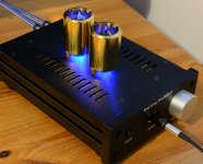
I reported about hum pickup from the two tubes. I have no "Earth" at the 230 VAC outlet which probably caused the problem. I found a solution to that problem. As picture shows I have shielded the two tubes and now hum is completely gone. I tested in CCS mode as this is the most hum sensitive mode. I also used the most hum sensitive tubes I have (RCA). Then I also used the head phones which was most hum sensitive.
The shields are made by Yamamoto. They use the shields for their phono preamp. Shields are gold plated bronze (4mm solid bronze). It is non-magnetic and it shields both electrical and magnetic according to Jac van de Walle from JacMusic where I got the shields from.
After this project the Student is a bit more Starving! ….it is a good name for an amp using golden shields!
It looks better live than on picture.
Attachments
Sounds Terrific - Can someone help me with the enclosure?
Hi All--
I ordered a Starving Student with enclosure on the day the latest batch was announced, and it arrived just a few days later, very quick, well packed. Unfortunately, the two tube sockets were missing, but Elena and Jason from the DIY Audio store responded immediately and had Pete Millet send out the sockets by mail right away. Thank you for unbelievably awesome customer service!
I had taken the time to assemble everything but the tube sockets, so when they arrived this afternoon, I put them in and quickly finished up construction.
From the start, when I plugged it in everything worked as it should. It sounded fantastic with my hifiman Massdrop HE-4XX headphones, just using my iphone as a source. As noted here, the tubes are very microphonic, which is a non-issue as far as I can tell. With my more sensitive Fiio FH5 IEMs, I could hear some tube noise when the music wasn't playing, but on the other hand, these IEMs have never sounded better. As far as I'm concerned, this is a winner, a terrific little easy-to-build project that will get a lot of use. My initial feeling is that I prefer the CCS sound, by the way, but it sounds great in both configurations.
I'm listening to it now as a preamp for a Dynaco ST-70, and it does the job well, though the taper of the volume pot works better with headphones than it does with this particular amp, as everything gets pretty loud pretty quick. I'll stick to using it primarily as a headphone amp, as I don'tneed another preamp.
I will also try this with a proper DAC and report back if I hear anything different, but I can say the my first impression is quite positive! I even get a kick out of the LED's in the tube sockets and wouldn't want to change that. .
The only issue I have is with the enclosure: the front plate does not seem to work with the power switch included in the kit. Based on the pictures in the online assembly instructions by Pete Millet and 6L6, this switch is slightly different from the one used in the past; it functions fine, fits the PCB fine, but it has a plastic piece at the base of the plastic pushbutton that doesn't clear the front plate of the enclosure. When the plate is on tight, it doesn't allow the switch to fully extend. I will either need to ream out the front plate (which I definitely DON'T want to do), or I'll have to track down a different on/off switch. Right now, I'm forced to use the enclosure without the front plate.
As far as I can tell, my problem is not a case of misalignment but a lack of compatibility with the power switch and the enclosure. Has anyone else had this problem? Does anyone have a solution? Do the folks at DIY Audio know that this power switch may be an issue, and do they have a solution? Or am I simply incompetent?
Thanks, Pete Millett and DIY Audio for a terrific product!
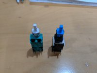
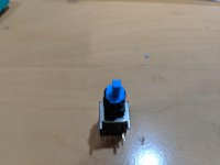
On the power switch... yes, there are two styles of switch. All but the first batch shipped with the black one (first photo). The issue is that the black one has a larger plate in front of the spring - it's square and not rounded. So it can hang up on the hole in the front panel, especially if the switch isn't soldered perfectly straight into the PCB. Make sure the switch is pushed all the way down into the PCB. You can help matters by clipping the corners off of the blue plastic plate with a pair of wire cutters, as shown in the second photo. You need to be careful to not cut too much, or the spring will escape...
It also helps to put a chamfer (countersink) on the inside of the panel (Actually, I though we did that...) A debur tool works great, but you can use a countersink, sandpaper, or even a knife to break the sharp edge on the inside of the hole.
On the power jack - I haven't seen a problem there. Are you sure it's soldered straight into the PCB? Sometimes the part might be a bit loose in the PCB holes, and it can move around while or before soldering.
Pete
Attachments
Hi Pete--
Thanks for the quick response! So, I trimmed the edges of the blue plastic plate that holds the spring, and it still didn't clear the panel. I trimmed a little more, and the problem remained, but there is now barely enough plastic left to hold the spring in place. It's compromised, but it hasn't completely self-destructed, and I suppose I could super glue the spring in place if it doesn't hold.
After all that trimming, I still had the problem with the blue plastic piece not clearing the back of the front plate, so I made a chamfer. It took some filing and working with a dremel before I figured out the best solution, which was to use a very large drill bit I had and drill a bigger hole partway into the back of the plate. This, finally, allowed the blue plastic bit to stop bumping against the back of the plate, and now the switch works, as long as the spring stays where it should. If others have the same problem, my recommendation is that you simply use a large drill bit to put in a countersink which will clear the switch.
By the way, I also have a problem on the back plate. I can get everything to line up, but the back plate is so thick it keeps the power supply plug from going all the way into the jack. At this point, having spent far more frustrating hours trying to make the enclosure work than it took to build the amp itself, I am simply going to use it without the back plate.
I'll be curious to see if anyone else has these problems or whether it simply comes down to incompetence on my part. As far as I can tell, I did put everything in correctly, but at this point I'm giving up. If others have the same problem, please let me know your solution. Meanwhile, I will listen to calming music on my headphones and try to let the frustration go.
We don't want anyone to have to have any trouble with this, so we'll be shipping replacement power switches free of charge to everyone who got one of these new ones with the square tab.
The helpdesk will be in touch within 24 hours to confirm your preferred shipping address.
The helpdesk will be in touch within 24 hours to confirm your preferred shipping address.
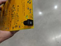
HEADPHONE JACK MIS-ALIGNED ?
I’ve read these interesting forums (thank you) for years and finally taken the steps of getting involved.
I couldn’t wait for the approved power switch to arrive; with all components populating the board I mounted the 3 rear connectors (perfect) then the front volume control + phone jack - seating firmly and soldering.
With the board mounted to the top panel + sides + rear, has anybody else had a problem with the front panel slanting up from the vol ctrl and being several mm higher on the power switch side when it is slipped over the volume control + phone jack? Both elements were right down onto the board.
I’m not having any luck removing the jack to loosen things up to re-visit the installation with un-soldered hardware.
My first three thoughts were an “oddball jack”, the fourth one was an “installation mess-up”.
If I can remove the jack, is it OK to RE-use it with the signal pin NOT protruding - are those holes plated-through?
Any helpful suggestions please?
Soldering iron goes nowhere near the new power switch yet : {
- Home
- The diyAudio Store
- Starving Student II Headphone Amplifier