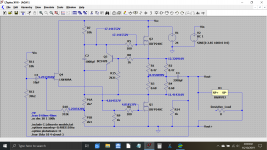
This shows you the typical voltages for a working amp, what you are looking for are gross variations. We know your midpoint voltage won't go above around 0.2 volts on the faulty channel, but that reading should reflect in errors elsewhere, so see where it falls down by measuring.
Attachments
The plot thickens. Instead of checking voltage I started by re-checking the resistors. Although I was very careful to place the resistors in the right place I'm getting some strange readings now that they are soldered and the amp is wired up:
Left Board
R8 = .687 (should be 1k)
R9=.5 (should be 1k)
R15=.687 (should be 2.21)
Right Board:
R8=.687 (should be 1k)
R9=.5 (should be 1k)
R11=8k (should be 10k)
r12=8.56k (should be 39.2)
All others are exact or pretty close.
Left Board
R8 = .687 (should be 1k)
R9=.5 (should be 1k)
R15=.687 (should be 2.21)
Right Board:
R8=.687 (should be 1k)
R9=.5 (should be 1k)
R11=8k (should be 10k)
r12=8.56k (should be 39.2)
All others are exact or pretty close.
You can not reliably check most resistors as long as they are soldered into a circuit because of interactions with other components.
The low supply voltage of the ACA means that any resistor over around 1k could not be damaged by a circuit fault because there just isn't enough voltage to generate the power needed to make the part fail.
Below around 1k and a fault putting the full 24 volts across the resistor could cause over dissipation. So the 100 ohms and the very low resistor values in the output stage are prime candidates for failure in an overcurrent situation.
Got it. Thanks very much. Prior to checking the resistor values I did also check some of the voltages and every one of them appeared to be off. Is this indicative of potential component damage?
I did remove the boards from the chasis and carefully inspected each solder point to make sure nothing was touching or potentially causing a short circuit.
Are there best practices in situations like this to work my way down a chain to identify root cause?
I did remove the boards from the chasis and carefully inspected each solder point to make sure nothing was touching or potentially causing a short circuit.
Are there best practices in situations like this to work my way down a chain to identify root cause?
If there was smoke then unfortunately yes, something will be damaged, however knowing the supply voltage is only 24 volts means that we can discount any failures in the physically smaller resistors that are under 1k.
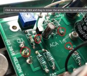
The first thing you need to do is try and establish what has failed now, at this moment in time. That will give a clue as to what has happened, and the way to do that is to measure and record the voltages at the key points in the circuit.
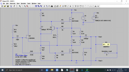
If you want to take this plain image of the circuit and then write all the voltages down that you measure then we should be able to compare to what we know should be present and determine what has happened.
The first thing you need to do is try and establish what has failed now, at this moment in time. That will give a clue as to what has happened, and the way to do that is to measure and record the voltages at the key points in the circuit.
If you want to take this plain image of the circuit and then write all the voltages down that you measure then we should be able to compare to what we know should be present and determine what has happened.
Attachments
Ok. I took several voltage readings but then I noticed something strange going on. At the V+ input in both boards the voltage is cycling what looks to be between 0v and 24v repeatedly and the LEDs are blinking at the same interval. Might that be something obviously incorrect?
That sounds like the power supply cycling in response to an overload and the output FET's are the only realistic low impedance path that could allow such current to flow.
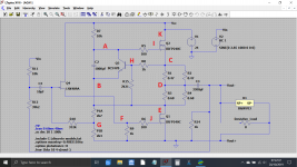
If you link out C2 (short it out with a bit of wire) which is the 1000uF cap that is across Q3 then the current should fall to near zero. If it does not then there is a problem around the upper FET.
In any case, I think you should do a full and careful visual inspection of the faulty board. Q3 regulates the current and so if there is a problem around this transistor then the current would be very high.
The fact you saw smoke at the beginning means that some parts will have failed... what you must do is find a reason why rather than just replacing them and seeing the same thing happen again.
We can apply a couple of tricks to help faultfinding such as you inserting a 300 or 500 watt type halogen bulb in series with the 24 volt DC supply to the faulty channel. We would then work from that point to try and determine the issue. The filament would be very low resistance at lowish current but would rise rapidly if there was a short anywhere.
The theory is sound (but untested on the ACA) and so you would first have to try the bulb across the 24 volt supply to make sure it does allow the PSU to start correctly. The bulb would glow even on such a low voltage.
That definitely sounds like what's happening. In fact the light on the power supply itself dims and brightens in sequence with the LEDs. So disappointing since I followed the steps in the build guide very carefully! In any case, thanks again for these troubleshooting tips. I'm sticking with this amp until I get it working!
One other thing that I forgot to mention is that one of the heat sinks gets very hot while the other does not. Is that indicative of the side with the bad board? I'm assuming the visual check is to look for any solders that are touching or wires that may touch the case?
One other thing that I forgot to mention is that one of the heat sinks gets very hot while the other does not. Is that indicative of the side with the bad board? I'm assuming the visual check is to look for any solders that are touching or wires that may touch the case?
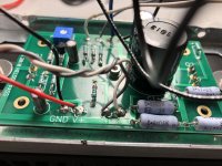
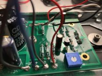
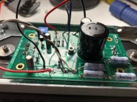
Here are a bunch of photos from several angles. Hopefully these are clear enough. Please let me know if you'd like close ups of any specific areas.
ACA images – Google Drive
ACA images – Google Drive
That definitely sounds like what's happening. In fact the light on the power supply itself dims and brightens in sequence with the LEDs. So disappointing since I followed the steps in the build guide very carefully! In any case, thanks again for these troubleshooting tips. I'm sticking with this amp until I get it working!
One other thing that I forgot to mention is that one of the heat sinks gets very hot while the other does not. Is that indicative of the side with the bad board? I'm assuming the visual check is to look for any solders that are touching or wires that may touch the case?
The heatsink question isn't definitive unfortunately because the ACA when operating normally does get hot...
That said I would probably suspect that the channel that is hot has an issue and also the channel that is cold.
The cold channel sounds like it is not drawing current (faulty) but that would not load the power supply.
Did you build these from the official kit or did you source the parts yourself?
Concentrate on one channel. I would disconnect the 24V supply to the HOT channel and lets see where the cold one is at with regard to voltage measurements. This cold channel could be the one that originally failed (smoked) and this now has some open circuit parts preventing current flow.
Can you list the voltages as per post #569 above and lets see what is going on.
Pictures
")
How to attach images to your posts.
Here are some of your images:
Attachments
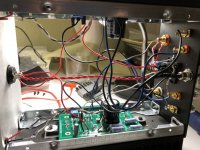

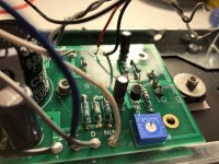
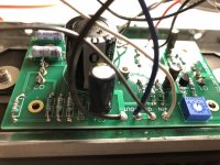
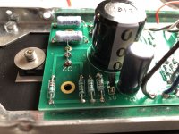
Things like this (also look at the underside of the board) need looking at. Don't be afraid to use a large tipped iron to put plenty of heat down. A small croc clip makes a good heat shunt that you can clip to the lead being soldered to protect the part from excess heat.
Attachments
Hi bobertbk,
First can I ask if you are using the V1.6 build instructions? (Amp Camp Amp V1.6 Build Guide - diyAudio Guides)
If so look down to Step 56 Troubleshooting.
It give the typical resistance and voltage readings (from a range of ACAs) and shows where to make the readings / checks. (It also relates them to the circuit diagram like mooly's post #569 is doing.) But please start with the resistance readings and let us know.
There is obviously a short or low resistance problem that is 'pulsing' the power supply. First locate which of the boards is at fault.
Un-solder the red wire from V+ on the 'cold' board and switch on again. If the pulsing stops the fault is on the cold board. And so on. Please identify which board is the problem say by 'white input board' or 'red input board'. It will be difficult to do any voltage checks if there is a fault pulling the power supply down...
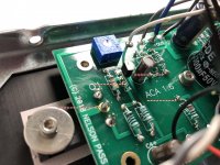
Then more generally there are a number of issues with your soldering. Several components are not soldered properly. This will let you down later if it is not causing a problem right now... Difficult to see too, but the RCA inputs look shorted? Can you check?
Alan
Beaten by mooly!
First can I ask if you are using the V1.6 build instructions? (Amp Camp Amp V1.6 Build Guide - diyAudio Guides)
If so look down to Step 56 Troubleshooting.
It give the typical resistance and voltage readings (from a range of ACAs) and shows where to make the readings / checks. (It also relates them to the circuit diagram like mooly's post #569 is doing.) But please start with the resistance readings and let us know.
There is obviously a short or low resistance problem that is 'pulsing' the power supply. First locate which of the boards is at fault.
Un-solder the red wire from V+ on the 'cold' board and switch on again. If the pulsing stops the fault is on the cold board. And so on. Please identify which board is the problem say by 'white input board' or 'red input board'. It will be difficult to do any voltage checks if there is a fault pulling the power supply down...
Then more generally there are a number of issues with your soldering. Several components are not soldered properly. This will let you down later if it is not causing a problem right now... Difficult to see too, but the RCA inputs look shorted? Can you check?
Alan
Beaten by mooly!
Attachments
Last edited:
Build Guid step 34 / 36
Hello to all!
I'm confused:
I build the ACA after the option C: Front switch: None; Rear switch: Power
and follow the guide as exactly as I can (because I don't know much about electronics).
The diagram @ step 34/3 shows the connection of the DC-jack to the switch in the middle pins of the switch:

but @step 36, the photo shows the connection is made @ the lower 2 pins (while the sketch is like @step 34):

and the middle pins connect to the PCBs.
Which one is right?
Thanks very much!
best
da.
PS added this comment in the build guide, might be a bit over the top, sorry...
Hello to all!
I'm confused:
I build the ACA after the option C: Front switch: None; Rear switch: Power
and follow the guide as exactly as I can (because I don't know much about electronics).
The diagram @ step 34/3 shows the connection of the DC-jack to the switch in the middle pins of the switch:
but @step 36, the photo shows the connection is made @ the lower 2 pins (while the sketch is like @step 34):
and the middle pins connect to the PCBs.
Which one is right?
Thanks very much!
best
da.
PS added this comment in the build guide, might be a bit over the top, sorry...
- Home
- The diyAudio Store
- Amp Camp Amp Kit 1.6/1.8