Hi,
Late to the game as usual. Thanks to Alan for sleuthing through this one, he is being so gracious with his time and efforts!
Gary,
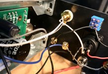
Looking through your pictures, I am wondering if you made sure that the black binding posts (like the red binding posts) also has a black plastic insulating spacer? It's unclear in the pictures due to the black on black contrast with the back panel. If there isn't an insulating spacer, then your speaker output signal will be shorted.
Hope you get it resolved! If you are in the U.S., I'll be happy to take a look, clean up/resolder the boards, etc...in exchange for shipping costs. But that wouldn't be very instructional for you and one of the goals here with the ACA kit is to make it a learning/iterative process.
Best,
Anand.
Hi Anand,
Thanks much for the response. I do want to try again to get this working. My goal in doing this build is less to have another amp than it is to learn more about how these devices work. I do appreciate your offer. Also, I did install the spacers as shown in the build guide.
Best,
Gary
I just wanted to send an update out on my 3 ACAs. I tested the amps again wired for bridged mono (RCA connected with switch flipped). The amps are definitely getting a good amount of gain now with my Marantz 7703 preamp. I also reran Audacity to make sure levels and any frequency dips in my setup were compensated properly.
I also tested in parallel mono but in that mode I didn't get the gain that I needed through my 3 custom Vapor Audio Stiff Breeze speakers. In bridged mono, I have been able to play my system and hear them at a decent volume - even enough volume to annoy my wife a bit (which means they are loud enough to back off and have a little bit of headroom available!).
One thing cool I found was this ADA Fruit IoT Relay that may be used to send a 12V DC voltage from my Marantz 7703 to automatically turn on the power to my 3 ACAs. It works perfectly to turn on the amps automatically when the Marantz powers on!
Anyway despite the fact that the ACAs are working pretty well now, I think as a theater system amps I still think they are a bit under-powered. I am going to keep them in my system for listening to audio for now (but would sell them if someone is interested), as I have been loving listening to Nick Drake and Mark Knopfler and my other favorites through these. But, for theater use I am going to try building 3 monoblock Class D amps (based on 3eaudio's TI amps recent group buy). Part of my rationale for this, is that I have another issue with the ACAs now, which is in an enclosed rack cabinet, they are getting a little bit too warm! They are fine if I leave the cabinet door open though.
Gary,
What is your source? Are you using the RCA inputs? If you flip the L/R RCA cables from your source does the faulty channel flip too?
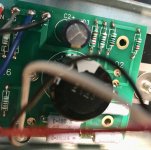
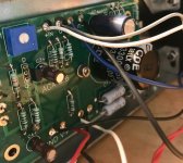
Also...the center pin of your red RCA looks very suspicious. There seems to be a lot of black carbonized gunk. Can you clean it up with some isopropyl alcohol and resolder? If you haven’t already please consider a Flux Removal spray. I use Chemtronics brand:
Chemtronics - ES1696 - Cleaner; Flux-Off No Clean Plus; Solvent cleaner; 12 oz. aerosol - Allied Electronics & Automation
Then I use Kimwipes:
MG Chemicals - 830-34133 - KIMWIPES DELICATE TASK WIPERS--Single Ply; 11.8x11.8in - Allied Electronics & Automation
Also consider purchasing some liquid flux. It really helps solder to flow into the joints. I use this:
GC Electronics - 10-4202 - Solder; 2 Oz.; Liquid - Allied Electronics & Automation
You can probably find cheaper alternatives or other online retailers.
Best,
Anand.
What is your source? Are you using the RCA inputs? If you flip the L/R RCA cables from your source does the faulty channel flip too?
Also...the center pin of your red RCA looks very suspicious. There seems to be a lot of black carbonized gunk. Can you clean it up with some isopropyl alcohol and resolder? If you haven’t already please consider a Flux Removal spray. I use Chemtronics brand:
Chemtronics - ES1696 - Cleaner; Flux-Off No Clean Plus; Solvent cleaner; 12 oz. aerosol - Allied Electronics & Automation
Then I use Kimwipes:
MG Chemicals - 830-34133 - KIMWIPES DELICATE TASK WIPERS--Single Ply; 11.8x11.8in - Allied Electronics & Automation
Also consider purchasing some liquid flux. It really helps solder to flow into the joints. I use this:
GC Electronics - 10-4202 - Solder; 2 Oz.; Liquid - Allied Electronics & Automation
You can probably find cheaper alternatives or other online retailers.
Best,
Anand.
Gary,
What is your source? Are you using the RCA inputs? If you flip the L/R RCA cables from your source does the faulty channel flip too?
Also...the center pin of your red RCA looks very suspicious. There seems to be a lot of black carbonized gunk. Can you clean it up with some isopropyl alcohol and resolder? If you haven’t already please consider a Flux Removal spray. I use Chemtronics brand:
Chemtronics - ES1696 - Cleaner; Flux-Off No Clean Plus; Solvent cleaner; 12 oz. aerosol - Allied Electronics & Automation
Then I use Kimwipes:
MG Chemicals - 830-34133 - KIMWIPES DELICATE TASK WIPERS--Single Ply; 11.8x11.8in - Allied Electronics & Automation
Also consider purchasing some liquid flux. It really helps solder to flow into the joints. I use this:
GC Electronics - 10-4202 - Solder; 2 Oz.; Liquid - Allied Electronics & Automation
You can probably find cheaper alternatives or other online retailers.
Best,
Anand.
Hi Anand,
I was getting a little frustrated at my inability to get the ACA working, so I decided to take a break for a while. I took another look yesterday. I got it working. I'd reflowed all the soldering I'd done but still no audio output in the right channel. I decided to completely rebuild the right input, this time using less solder than previously. That did it. This amp is really amazing. I'm a tube guy but I really like what I'm hearing. Thanks very much for your help. It was your suggestion that got me to take a closer look at the ACA. You were absolutely right.
Gary
Hi Anand,
I was getting a little frustrated at my inability to get the ACA working, so I decided to take a break for a while. I took another look yesterday. I got it working. I'd reflowed all the soldering I'd done but still no audio output in the right channel. I decided to completely rebuild the right input, this time using less solder than previously. That did it. This amp is really amazing. I'm a tube guy but I really like what I'm hearing. Thanks very much for your help. It was your suggestion that got me to take a closer look at the RCA. You were absolutely right.
Gary
Gary!
That’s awesome!
See one. Do one. TEACH one!
Enjoy!
Anand.
")
Hi Jim,
Thanks for the response. This forum is amazingly helpful and supportive. It's a very different experience than the audiophile forums I typically frequent. It's really refreshing.
I have to say that I'm stunned at how good this amp sounds. It's actually replaced the Cary Audio hybrid amp I was using. How can that be? I've heard Pass Labs gear many times at audio shows but the First Watt stuff is new to me. I know it's only been a few days but at this point I'm certain this is a sound and technology I want to pursue. I am looking for new amplification for my 91db efficient speakers. I live in a typically small NYC apartment so high volumes with lots of power aren't required.
What I'd like is a Class A amp delivering somewhere around 25 watts into 8 ohms. As good as the ACA is it's a little under powered for my speakers. I've thought about building another and using them in bridged mono mode but I'd prefer one stereo box. I know I may not be ready for a more challenging kit but I'd really love to build another amp. I'm going to do more soldering practice while I wait. Any suggestions for a new project?
Best,
Gary
I second that. The M2 is my favorite amp in my long history of being an audio nut.
I second that. The M2 is my favorite amp in my long history of being an audio nut.
Thanks to both of you. I'm looking through the M2 build guide now. So far it looks like a great choice. I'm definitely going to have questions.
Best,
Gary
one blue diode active, no heat from heatsinks, how to reflow?
Great to see that persistence and stepping through carefully pays off with a working amp. I've built mine over a few spare hours in the past week or so and must have bad soldering or mis-wiring.
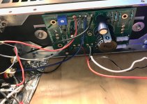
If I have one diode lit, the other one not, no heat from the heatsinks, and of course no sound... where do I start with troubleshooting?
I'd like to try re-soldering everything. How do I get the bits that are in there now out -- how to remove all the solder that's now holding things in place?
Hi Anand,
I was getting a little frustrated at my inability to get the ACA working, so I decided to take a break for a while. I took another look yesterday. I got it working. I'd reflowed all the soldering I'd done but still no audio output in the right channel. I decided to completely rebuild the right input, this time using less solder than previously. That did it. This amp is really amazing. I'm a tube guy but I really like what I'm hearing. Thanks very much for your help. It was your suggestion that got me to take a closer look at the RCA. You were absolutely right.
Gary
Great to see that persistence and stepping through carefully pays off with a working amp. I've built mine over a few spare hours in the past week or so and must have bad soldering or mis-wiring.
If I have one diode lit, the other one not, no heat from the heatsinks, and of course no sound... where do I start with troubleshooting?
I'd like to try re-soldering everything. How do I get the bits that are in there now out -- how to remove all the solder that's now holding things in place?
I wouldn't start pulling parts out tbh, that's a recipe for disaster. Look at each part in turn, confirm its correct and correctly orientated and then reflow the joints if they look suspect.
A suitable iron and bit should make a good joint in just two or three seconds. Always use suitable solder as well. The joint should be bright and shiny.
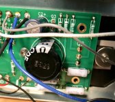
Maybe post a picture of the board and the joints and we can advise how best to proceed.
A suitable iron and bit should make a good joint in just two or three seconds. Always use suitable solder as well. The joint should be bright and shiny.
Maybe post a picture of the board and the joints and we can advise how best to proceed.
"I wouldn't start pulling parts out tbh, that's a recipe for disaster. Look at each part in turn, confirm its correct and correctly orientated and then reflow the joints if they look suspect.
A suitable iron and bit should make a good joint in just two or three seconds. Always use suitable solder as well. The joint should be bright and shiny.
Maybe post a picture of the board and the joints and we can advise how best to proceed."
__________________
Thanks! I'll do that. A few pictures should be attached.
Attachments
-
 IMG_9723.jpg204.4 KB · Views: 738
 -
 IMG_9729.jpg362.9 KB · Views: 91
 -
 IMG_9736.jpg362.5 KB · Views: 90
 -
 IMG_9751.jpg269.3 KB · Views: 86
 -
 IMG_9747.jpg334.3 KB · Views: 98
 -
 IMG_9744.jpg348.1 KB · Views: 107
 -
 IMG_9732.jpg349.4 KB · Views: 268
 -
 IMG_9742.jpg355.9 KB · Views: 264
 -
 IMG_9728.jpg294.9 KB · Views: 273
 -
 IMG_9735.jpg243.7 KB · Views: 283
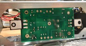
OK, so that definitely looks salvageable to me.
I can see a lot of joints that have virtually no solder on them so what you need to do is reflow these correctly. I'm assuming your iron is OK and my choice would be to use a fairly large tip for this as that will hold the heat. A good iron and tip really is crucial.
Apply the iron to a joint while at the same time applying solder to the iron/joint interface. Don't be afraid to put a little pressure on the iron to really contact the board. The solder should flow instantly around and into the joint. If it doesn't then something in the technique or equipment is amiss.
Its important not to overheat small parts and one way to avoid that is to mentally count... one, two, three and four. Any longer is to long. You should ideally only need around a couple of seconds per joint on the small stuff.
A tiny croc clip attached to the component lead on the opposite side of the board is a great way to reduce heat into a component although you shouldn't really need to be doing that here.
OK, so that definitely looks salvageable to me.
I can see a lot of joints that have virtually no solder on them so what you need to do is reflow these correctly. I'm assuming your iron is OK and my choice would be to use a fairly large tip for this as that will hold the heat. A good iron and tip really is crucial.
Apply the iron to a joint while at the same time applying solder to the iron/joint interface. Don't be afraid to put a little pressure on the iron to really contact the board. The solder should flow instantly around and into the joint. If it doesn't then something in the technique or equipment is amiss.
Its important not to overheat small parts and one way to avoid that is to mentally count... one, two, three and four. Any longer is to long. You should ideally only need around a couple of seconds per joint on the small stuff.
A tiny croc clip attached to the component lead on the opposite side of the board is a great way to reduce heat into a component although you shouldn't really need to be doing that here.
Most excellent soldering tips above.
To re-emphasize - if you're going past the 4 count to get solder to flow, your
heat is too low. If solder melts but balls up, surfaces are not clean and/or flux is not doing its' job (which is to clean the joint so solder will flow and adhere).
Jng, if you look at the schematic, the led is only one resistor after the voltage input. If that one is not lighting up, you may have an issue with the voltage input, the ground or something very basic that is missing.
So I'd start there. Make sure that voltage is reaching the PCB before taking the PCB apart.
Good luck,
Rafa.
So I'd start there. Make sure that voltage is reaching the PCB before taking the PCB apart.
Good luck,
Rafa.
Jng,
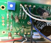
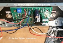
There is a more obvious problem with your build, you have put Q3 and Q4 in the wrong places...
Q3 (ZTX450) has the 2 flatter sides. Q4 has the rounded shape and one flat side.
See the pictures. See the pictures please.
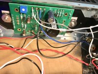
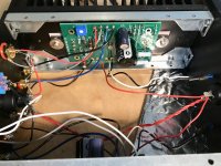
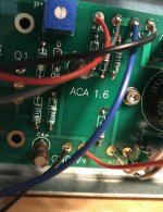
The other problem, as Mooly and Mazeppa has pointed out, is that there are numerous joints that are not soldered. Both on the boards and on the wiring.
You will need to remove both Q3s and Q4s first. You need to use a 'solder sucker' or 'solder braid' to remover the solder holding them in.
Then you can inspect and correct all the poor joints one a a time...
It will work at the end I'm sure, Alan
There is a more obvious problem with your build, you have put Q3 and Q4 in the wrong places...
Q3 (ZTX450) has the 2 flatter sides. Q4 has the rounded shape and one flat side.
See the pictures. See the pictures please.
The other problem, as Mooly and Mazeppa has pointed out, is that there are numerous joints that are not soldered. Both on the boards and on the wiring.
You will need to remove both Q3s and Q4s first. You need to use a 'solder sucker' or 'solder braid' to remover the solder holding them in.
Then you can inspect and correct all the poor joints one a a time...
It will work at the end I'm sure, Alan
Attachments
Thanks, Rafa, Alan, and all, for soldering tips and careful inspection of those pics!
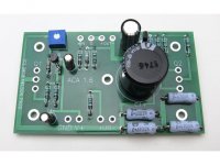
Each time I compare my circuit to reference pictures and diagrams on the how-to, it makes a little more sense. I didn't see the difference between Q3 and Q4 in the first go-round.
I used an iron and tip from a $30 Anbes kit from Amazon and Cardas quad solder. It would be nice to have extra hands; looks like tools are available from Amazon that will hold things in place while soldering.
I was worried about applying too much solder to the joints and must have erred quite a bit on the side of not enough. What should I use to vent or absorb solder fumes? We're in the northeast, so opening windows is an option but not my favorite.
- Home
- The diyAudio Store
- Amp Camp Amp Kit 1.6/1.8