Did you re-run Audessey in the Marantz when you added the amps?
No, I didn't rerun Audessey but that is definitely something that I can try. I'll give that a shot in a couple of weekends from now... sadly that is probably the next opportunity I'll have to do some playing around with everything. Thanks for the suggestion.
Altering R12 will prove one way or the other whether the preamp is struggling as altering this resistor will not alter the input impedance.
Definitely worth trying that first.
I am going to try the Audessey thing and if that doesn't work I will try changing R12 on one of the amps. Either way I'll report back when I can!
Yes from what we can see everything is installed ok.
Go to the build guide, Amp Camp Amp V1.6 Build Guide - diyAudio Guides
and see Step 56 ''Troubleshooting''.
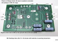
Do the resistance and voltage checks and let us know the results, please.
Here is the measure :
Attachments
Fog,
Are you using XLR in or RCA bridged mono? Your speakers are 4ohm, so RCA paralleled mono would be the way to go.
I was using XLR when testing with the Marantz. Funnily enough when I was getting decent volume on my small bookshelf speakers, I had it in bridged SE RCA mode (but just driven from a phone). Should I expect another 3dB of gain by switching to RCA bridged?!
Last edited:
I was using XLR when testing with the Marantz. Funnily enough when I was getting better gain on my small bookshelf speakers, I had it in bridged SE RCA mode (but just driven from a phone). Should I expect another 3dB of gain by switching to RCA bridged?!
I just rechecked the ACA Operation Modes page and it seems to imply that I would only get 5 Watts of power out to 4 ohms in XLR mode, but 16 Watts out in parallel mono!? It sounds like that may be the best approach for me. Looks like I also double my damping factor which could potentially tighten up my bass. But wondering how much noise and distortion will suffer as a result. Is the expectation that those are doubled as well?
Here is the measure :
Start by checking R7.
Top right hand corner and should be 10k ohms.
You have 24 volts one side of it (from Q2 D) and only 2.8 volts on the other (Q3 c).
It could be high resistance / open circuit or not soldered in properly.
Take a resistance reading, meter on 20k ohms, from the top of R5 to the D pin of Q2. It should read nearly 10k ohms after a few seconds.
Alan
Hi there,
R7 measure 3.2K (top) and 0.5K (to pin D of Q2).
R5 measure 3.3K to R7 to pin D of Q2.
So you think is a bad solder joint?
Sorry, not from those results...
If it was a poor connection you would expect more than 10k not less.
But I am a little confused by the way you have shown the results too, I do not understand what 'and 0.5k' or '3.3K to R7 to pin D' means.
So as there are no numbers on the resistance picture on post #404, can you check them again and record the values please? Alan
Sorry, not from those results...
If it was a poor connection you would expect more than 10k not less.
But I am a little confused by the way you have shown the results too, I do not understand what 'and 0.5k' or '3.3K to R7 to pin D' means.
So as there are no numbers on the resistance picture on post #404, can you check them again and record the values please? Alan
All measure are form the gound.
I measure 3.2K between R5 and R7
I measure 500 Ohms between R7 the pin D of Q2.
I measure 3.3K between R5 and pin G of Q2.
Sorry my mistake.
All measure are form the gound.
I measure 3.2K between R5 and R7
I measure 500 Ohms between R7 the pin D of Q2.
I measure 3.3K between R5 and pin G of Q2.
Sorry my mistake.
No mistake, just a different method I think.
And I am still not quite with you yet. So let's try something else.
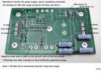
Unsolder one end of R7, measure its resistance. (Should be 10k)
Next unsolder one end of R5, measure its resistance. (Should be 100r)
Leave them out of circuit for the next test.
Now put the Black meter lead on the ground wire.
Measure the resistance from ground to S, then from ground to G and again from ground to D of Q2.
Let us know the results. Alan
Why? There is a unwritten standard for audio equipment power switches, it's up, in, or clockwise to turn power on.
In or clockwise is common for on but outside the US - down is common for on. Lots of countries outside the US have powersockets/outlets with switches on them that operaate down as on and the same with light switches.
Vive la difference!
")
Why? There is a unwritten standard for audio equipment power switches, it's up, in, or clockwise to turn power on.
+1
It has to be down for on otherwise how do you see the red dot on top that tells you it's switched on? Plus, my toaster is down for on!
- Home
- The diyAudio Store
- Amp Camp Amp Kit 1.6/1.8