Re-check the value of all the resistors with the meter against the build guide and online pictures and ensure you haven't got any in the wrong holes. I almost put R13 value resistor where R14 should go because it goes R11 R12 R14 across the board. Check your soldering looks nice and shiny and smooth - the metal should flow easily.
I bought some solder from a DIY audio supplier containing silver a while back and it was nasty to use and tricky to make a good joint. - I went back to 60% Tin 40% lead for my ACA build. Take your time and re-check everything it will be worth it.
I bought some solder from a DIY audio supplier containing silver a while back and it was nasty to use and tricky to make a good joint. - I went back to 60% Tin 40% lead for my ACA build. Take your time and re-check everything it will be worth it.
I guys, after assembling my amp, I plug it to speaker and my phone to see if it will work. One channel work fine, but the other was dead. Check the solder, do some resoldering, and now the channel have a sound, but very weak and distorted. I try to adjust the bias after 15 minutes but it limits me to 7V fully open. I measure the voltage according to the voltage chart on the build guide, and pin S of Q4 measure 1V instead of 4.7V and pin D of Q1 measured 7V. Have you any idea what is going wrong ?
Hi,
Also make sure Q4 and Q2 are in the correct places and the right way round and are all the capacitors in the right way round too?
Then could you post some good clear pictures of your boards and chassis please so we can take a look as well?
Alan
Last edited:
It's interesting to see how neat and tidy some peoples kits look compared to others - that looks exceptionally neat")
Thank you Steve
Just one thing bothers me about the ACA - the builld shows power switch mounted and wired the wrong way up for those of us that are used to switches on power outlets and lights.
In Aus, NZ, UK all switches from monsters in switch rooms to every socket in peoples homes operate down as on. Food for thought.
In Aus, NZ, UK all switches from monsters in switch rooms to every socket in peoples homes operate down as on. Food for thought.
In Aus, NZ, UK all switches from monsters in switch rooms to every socket in peoples homes operate down as on.
AND your toilets flow the opposite direction! You guys really are backwards down there!!
In the US, a single light switch will be wired up for on.
I've never seen a power switch on commercial audio equipment where up, or clockwise, didn't turn the power on. There may of course be the odd example, but I worked in a shop where 2nd hand equipment was it's profit center, so I've likely seen more than the average bear...
Re-check the value of all the resistors with the meter against the build guide and online pictures and ensure you haven't got any in the wrong holes. I almost put R13 value resistor where R14 should go because it goes R11 R12 R14 across the board. Check your soldering looks nice and shiny and smooth - the metal should flow easily.
I bought some solder from a DIY audio supplier containing silver a while back and it was nasty to use and tricky to make a good joint. - I went back to 60% Tin 40% lead for my ACA build. Take your time and re-check everything it will be worth it.
Ok I will do that. Strange because I assemble the two amps simultaneously.
Ok, selling my 3 ACAs for $360 plus shipping
So I haven't gotten one bite regarding finding my 3 ACAs a new home/owner, so I was wondering if I should try to stick with these and investigate why I am not getting enough volume output. I have a Marantz AV7703 preamp and was wondering if that is not a good fit to drive the ACAs?
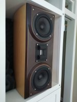
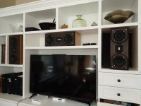
I am driving custom kit Vapor Audio Stiff Breeze speakers that took me about 100 hours to build. They sound fantastic and were quite a bit more expensive than the amps, so I really don't want to replace those. Secondly, I even had a custom home theater cabinet built to house my 3.1 system and incorporate everything so that it would have a high WAF (cabinet shown below).
I did not build the speakers to biamp them but that is an option since there are discrete crossovers for the low and high side, but I am not sure that I am willing to spend another 1150 on another set of 3 ACAs. Plus that will only get me another 3 dB potentially. Plus my closed cabinet cannot fit another 3 ACAs nor another 45 Watts of heat!
I could potentially also just repurpose the cases and resell the stuffed ACA PCBs? I was also wondering if the ACAs with reduced rail voltage and modified gain could be used as super high quality input buffers?
Any ideas greatly appreciated,
Ryan
So I haven't gotten one bite regarding finding my 3 ACAs a new home/owner, so I was wondering if I should try to stick with these and investigate why I am not getting enough volume output. I have a Marantz AV7703 preamp and was wondering if that is not a good fit to drive the ACAs?
I am driving custom kit Vapor Audio Stiff Breeze speakers that took me about 100 hours to build. They sound fantastic and were quite a bit more expensive than the amps, so I really don't want to replace those. Secondly, I even had a custom home theater cabinet built to house my 3.1 system and incorporate everything so that it would have a high WAF (cabinet shown below).
I did not build the speakers to biamp them but that is an option since there are discrete crossovers for the low and high side, but I am not sure that I am willing to spend another 1150 on another set of 3 ACAs. Plus that will only get me another 3 dB potentially. Plus my closed cabinet cannot fit another 3 ACAs nor another 45 Watts of heat!
I could potentially also just repurpose the cases and resell the stuffed ACA PCBs? I was also wondering if the ACAs with reduced rail voltage and modified gain could be used as super high quality input buffers?
Any ideas greatly appreciated,
Ryan
Attachments
When you say not enough volume, do you mean the sound is clear and undistorted but just not loud enough? If so then I assume your preamp volume control is maxed out as well.
If so then you could try increasing R12 to increase the gain. That would at least tell you if the ACA was basically suitable for your use. Try an 82k or 100k in place of the 39k2
If so then you could try increasing R12 to increase the gain. That would at least tell you if the ACA was basically suitable for your use. Try an 82k or 100k in place of the 39k2
Thanks Mooly. I can play at clear and undistorted levels but at lower volumes - around conversation level, maybe just slightly higher. The Marantz can definitely drive the input higher but the sound gets quite a bit distorted. It is really broken up sounding by the time I get it near volumes for watching TV or movies from our typical seating position (about 10-12 feet from the speakers). To get it that volume I have to bring the Marantz preamp to about 80-85 out of 100, so it could be the Marantz distorting, though that I think it is a pretty high-quality preamp unit and don't suspect it would distort to the degree that I am hearing. For comparison I usually have the volume set about 55-58 to watch movies with my other amp.
Edit: I also should mention that we rarely watch movies and TV at very high levels, no where near "reference" levels. Also, thank you Mooly for pointing out to vary the R12 resistor to increase the gain and experiment with this.
Edit: I also should mention that we rarely watch movies and TV at very high levels, no where near "reference" levels. Also, thank you Mooly for pointing out to vary the R12 resistor to increase the gain and experiment with this.
Last edited:
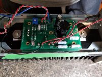
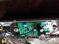
Well, I recheck that everything was in its place, Redone all the solder. Still no output. When trying to setup the bias, i can got to 7V max with potentiometer fully open. Hre a picture of the faulty channel :
Hey Sidsmith, the caps all look fine and the solder joints that I can see all look really clean and good. I can't really tell if all the resistors are correct. Especially the 3 hiding behind the big cap. Also did you double check orientation of the Q3 transistor which also can't be seen from your photo? Lastly, you might want to do an impedance check on the input RCA and speaker terminals to ensure you don't have a short there?
Hey Sidsmith, the caps all look fine and the solder joints that I can see all look really clean and good. I can't really tell if all the resistors are correct. Especially the 3 hiding behind the big cap. Also did you double check orientation of the Q3 transistor which also can't be seen from your photo? Lastly, you might want to do an impedance check on the input RCA and speaker terminals to ensure you don't have a short there?
Thank you for your king words !
Q3 seems ok.
How did you do an impedance test ? I am bit of a novice but a quick learner !
Attachments
Just one thing bothers me about the ACA - the builld shows power switch mounted and wired the wrong way up for those of us that are used to switches on power outlets and lights.
In Aus, NZ, UK all switches from monsters in switch rooms to every socket in peoples homes operate down as on. Food for thought.
This like many details was agonized over. In the end, being a primarily US product, with a US plug, sold from the US, we went with the US convention of power switch up = on. For those who really want switch down = on, you can dremel a second switch alignment notch recess in a few seconds on the opposite side, and mount the switch upside down. We didn't include a notch on both sides as the tolerance for mounting a 19mm Vandal Switch in its place would mean it would be impossible to cleanly mount the Vandal and not have a gap from one or the other the alignment notch. At the end of the day, it's a DIY product, and we didn't want to restrict options unnecessarily, so this seemed to be a good compromise between these many possible desires from builders.
Last edited:
Thanks Mooly. I can play at clear and undistorted levels but at lower volumes - around conversation level, maybe just slightly higher. The Marantz can definitely drive the input higher but the sound gets quite a bit distorted. It is really broken up sounding by the time I get it near volumes for watching TV or movies from our typical seating position (about 10-12 feet from the speakers). To get it that volume I have to bring the Marantz preamp to about 80-85 out of 100, so it could be the Marantz distorting, though that I think it is a pretty high-quality preamp unit and don't suspect it would distort to the degree that I am hearing. For comparison I usually have the volume set about 55-58 to watch movies with my other amp.
Edit: I also should mention that we rarely watch movies and TV at very high levels, no where near "reference" levels. Also, thank you Mooly for pointing out to vary the R12 resistor to increase the gain and experiment with this.
Altering R12 will prove one way or the other whether the preamp is struggling as altering this resistor will not alter the input impedance.
Definitely worth trying that first.
Well, I recheck that everything was in its place, Redone all the solder. Still no output. When trying to setup the bias, i can got to 7V max with potentiometer fully open. Hre a picture of the faulty channel :
Yes from what we can see everything is installed ok.
Go to the build guide, Amp Camp Amp V1.6 Build Guide - diyAudio Guides
and see Step 56 ''Troubleshooting''.
Do the resistance and voltage checks and let us know the results, please.
Didn't one of the other guys posting find that it was the board reading higher volts that was the cause of the same problem? taking more than its allocated share?Yes from what we can see everything is installed ok.
Go to the build guide, Amp Camp Amp V1.6 Build Guide - diyAudio Guides
and see Step 56 ''Troubleshooting''.
Do the resistance and voltage checks and let us know the results, please.
It's easy to damage the plastic washers on the speakers posts so that they aren't insulating the posts from the chassis too. Worth unscrewing those to check nothing is pinched.
- Home
- The diyAudio Store
- Amp Camp Amp Kit 1.6/1.8