Because the ACA inverts the signal and in order to preserve correct phase the markings on the rear panel speaker sockets are the opposite of what you expect. The Red + terminals go to ground in the official build and the Black - terminal goes to the amplifier output.
(Marking it that way ensures correct phase when the user connects their speakers i.e. speaker plus to amplifier plus when using the amp as a normal stereo unit)
This means the - terminals are the live ones. In bridge mode the speaker goes between - and - with the Red + terminals on each channel not being used.
The switch needs to be in the position that connects the 39k from the left channel output to the right channel input as shown here. In the diagram here that means the centre top pin and top right pin of the switch are connected when the switch is in the bridged position. The right input red RCA socket is left unused.
")
An LED wouldn't blow from reversing polarity, it would blow from too much current. What value do you have in the R13 position?Burned out almost all my LEDs before I figured out that I had the wires reversed in polarity...DERP. Does anyone have a Digi-key replacement part number for the blue LEDs?
33.2k resistor in R13 (verified by measurement). And I get 23.9v DC at the + terminal for the LED. Also verified resistance and placement of all other resistors and visually checked the caps and transistors. Kinda stumped as to what could be wrong, although this is my very first foray into circuits and electronics, so could use whatever help I can get!An LED wouldn't blow from reversing polarity, it would blow from too much current. What value do you have in the R13 position?
The amp seems to perform just fine sonically, FWIW.
If there is no functioning LED in place, you will just see what voltage is before the resistor. You need a load (In this case, the LED) to suck the voltage down to the rating of the LED which is usually around 2v or lower. 6l6's link to the assortment pack looks fun. I threw that in my cart as well.
Hey all, I appear to be missing two 10kohm resistors for the R13 spot. I may have never recieved them, or may have misplaced them. Either way, I need two 10k ohm resistors, will any 10k ohm resistor do?
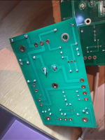
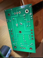
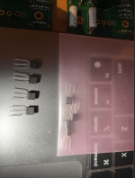
On another note, I can't tell how to identify which transistors are meant to go in the Q3 and Q4 spots on the circuit board. From what I can tell they are all the same, but the schematics have different ID#'s listed.
Also, while you're at it. Any input or thoughts on my soldering? It's my first attempt and I'm a little wary of it.
Attachments
-
 Screen Shot 2023-01-08 at 1.00.46 PM.png568.8 KB · Views: 90
 -
 Screen Shot 2023-01-08 at 1.01.08 PM.png659.9 KB · Views: 89
 -
 Screen Shot 2023-01-08 at 1.01.22 PM.png625.8 KB · Views: 89
 -
 Screen Shot 2023-01-08 at 1.01.32 PM.png645.5 KB · Views: 91
 -
 Screen Shot 2023-01-08 at 1.04.23 PM.png831.2 KB · Views: 86
I'm using a Hakko fx-888D Iron, Sparkfun Lead free solder (water soluble flux core) and in terms of technique I pretty much hold the iron to the joint for a moment and then apply the solder underneath the iron above the joint and hope for the best haha. I run the iron at 700 Farenheit.Tell us about your soldering equipment, material, and technique. What Iron/tip? What solder? What temperature? What's your technique? What teaching resources have you used (videos, books, practice board)?
Wow, gotta say I'm really impressed by how generous and keen to help everyone here seems to be. What a great community! Unfortunately I can't seem to figure out how to PM you on here but if you'd like to PM me first I'd be happy to send you my address. Thanks 6L6!That’s the wrong small transistor pack. PM me your post address and I’ll send proper ones.
Lead free solder is, well, awful. I’ll send you some real solder as well.
R13 is now 33.2k
Hey all, I appear to be missing two 10kohm resistors for the R13 spot. I may have never recieved them, or may have misplaced them. Either way, I need two 10k ohm resistors, will any 10k ohm resistor do?
On another note, I can't tell how to identify which transistors are meant to go in the Q3 and Q4 spots on the circuit board. From what I can tell they are all the same, but the schematics have different ID#'s listed.
Also, while you're at it. Any input or thoughts on my soldering? It's my first attempt and I'm a little wary of it.
I just completed the build of V1.8. I have power to both boards, bias was set to 20V. I’m using a Fiio m15 as source. I’m using a set of Klipsch RP-280F speakers. Both channels play however I must turn the Fiio to almost full output before I get any music and it is distorted. I did test all the resistors individually before populating the board with them. I went through the Step56 Troubleshooting Guide. Seeing as though it is late in the evening I was only able to test the right board. I put what the spec is supposed to be before what the actual value is.
Right Channel Bias 20v
Q1 Ohms
S 0-.2
D 5.2k-4.63k
G 1k-.621k
R10 G Ohms
335k-330k
Q4 D
1k-.522k
R9 S
1k-.521k
R15
B 5.8k-5.31k
E 5.2k-4.62k
Q2
G 11k-10.52k
D 1k-.523
S 5.2k-4.62k
R5
C 10.9k-10.47k
Right Channel Bias 20v
Q1 Ohms
S 0-.2
D 5.2k-4.63k
G 1k-.621k
R10 G Ohms
335k-330k
Q4 D
1k-.522k
R9 S
1k-.521k
R15
B 5.8k-5.31k
E 5.2k-4.62k
Q2
G 11k-10.52k
D 1k-.523
S 5.2k-4.62k
R5
C 10.9k-10.47k
Resistance checks in circuit I'm afraid are very inconclusive.
The important first checks are:
1/ Is the supply voltage correct (24 volts on Q2 Drain... the middle pin)
2/ The midpoint voltage should be around 12 volts. This is the middle pin of Q1
3/ The FET's should be running equally hot when powered up.
4/ R1, R2, R3 and R4 are the only ones that can be checked in circuit because they are so low in value. Measure and make sure you read around 0.235 ohms across R1 and 0.34 ohms across R3. These are the combined parallel value and may be hard to measure due to being so low. If your meter shows them as 'short' then that is fine. We are making sure you haven't fitted something to high in value such 47 ohm or 68 ohm.
Thanks...
The midpoint voltage at 20v is the problem here as it should be approx half the supply voltage.
First thought has to be a problem around the input FET. If it is non conducting you would get the voltages you are seeing.
What is the voltage on R6? (it doesn't matter which end you measure to)
What is the voltage on R10? This is the gate of the input FET.
Were the input FET's bought from the diyAudio store or from elsewhere?
Other possibilities are a problem with the connection from Q1 gate via R6 to the input FET. Confirm you measure 100 ohms from the gate pin of Q1 itself (measure from the pin and not the board) to the input FET source pin. You can check that in circuit. It should read approx 100 ohms.
If you connect a 2.2 or 2.7k resistor across the input FET (from Drain to Source) the midpoint voltage should fall to just a volt or so. Q2 will (should) get very hot and Q2 should be cold if you do this so limit the time testing to a minimum. If the midpoint volts does drop right down then this shows the output stage is basically OK.
If both channels are the same it suggests a common cause and the input FET would be the first suspect.
- Home
- The diyAudio Store
- Amp Camp Amp Kit 1.6/1.8