@ ryan391
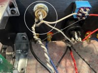
Please look carefully at the RCA (input) jacks. The white one is shorted with solder, 1247 image. Difficult to see the red one.
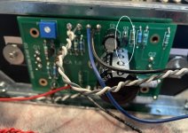
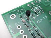
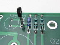
Then Q3 in the 1242 image is wrong. The ZTX450 transistor has two flat sides, have a look at the build guide, there is a subtle difference in shape for Q3 and Q4... (The fully round rear face one is the 2SK170 'Q4' and the flatter rear face transistor is the ZTX450 'Q3'. If you have mixed them up you need to swap them to their correct positions.)
You do need to master the multimeter next as you need resistance and voltage readings to move further forward. Good luck, Alan.
Please look carefully at the RCA (input) jacks. The white one is shorted with solder, 1247 image. Difficult to see the red one.
Then Q3 in the 1242 image is wrong. The ZTX450 transistor has two flat sides, have a look at the build guide, there is a subtle difference in shape for Q3 and Q4... (The fully round rear face one is the 2SK170 'Q4' and the flatter rear face transistor is the ZTX450 'Q3'. If you have mixed them up you need to swap them to their correct positions.)
You do need to master the multimeter next as you need resistance and voltage readings to move further forward. Good luck, Alan.
Attachments
Last edited:
@ryan391
What I’m getting at in my post above is that you may have one or two channels that are working. If you’re getting readings (between middle pin of Q1 and ground) of 7.7 Vdc on one and 12Vdc on the other, they may just need to be balanced. I would work at getting one channel at a time up and running. You need a way to distinguish one channel from another…like amplifier 1 right channel or amplifier 2 left channel. When you post pictures use that same format so we know which board we’re looking at. Once again use that same format when posting measurements.
What I’m getting at in my post above is that you may have one or two channels that are working. If you’re getting readings (between middle pin of Q1 and ground) of 7.7 Vdc on one and 12Vdc on the other, they may just need to be balanced. I would work at getting one channel at a time up and running. You need a way to distinguish one channel from another…like amplifier 1 right channel or amplifier 2 left channel. When you post pictures use that same format so we know which board we’re looking at. Once again use that same format when posting measurements.
No, Acutually Q2 middle pin is 24VIf you have a 7.7 Vdc reading between the middle pin of Q1 and ground (buss) then moving the red probe to the middle pin of Q2 you should have a reading of ~16.3 Vdc. Please confirm.
Will do, I have a busy day today. Going to do the suggested fixes above, cleaning up sloppy solder. and will work Sunday to take better pics@ryan391
What I’m getting at in my post above is that you may have one or two channels that are working. If you’re getting readings (between middle pin of Q1 and ground) of 7.7 Vdc on one and 12Vdc on the other, they may just need to be balanced. I would work at getting one channel at a time up and running. You need a way to distinguish one channel from another…like amplifier 1 right channel or amplifier 2 left channel. When you post pictures use that same format so we know which board we’re looking at. Once again use that same format when posting measurements.
As I look closer at Q3 and Q4 each amp has different pieces. I will post pics later or sunday. This may be my problem. Some are flatter others are rounded. I need to figure out what goes where and fix@ ryan391
Please look carefully at the RCA (input) jacks. The white one is shorted with solder, 1247 image. Difficult to see the red one.
Then Q3 in the 1242 image is wrong. The ZTX450 transistor has two flat sides, have a look at the build guide, there is a subtle difference in shape for Q3 and Q4... (The fully round rear face one is the 2SK170 'Q4' and the flatter rear face transistor is the ZTX450 'Q3'. If you have mixed them up you need to swap them to their correct positions.)
You do need to master the multimeter next as you need resistance and voltage readings to move further forward. Good luck, Alan.
Q3 and Q4 - Have a careful look at steps 11 and 12 ''small transistors'' of the build guide (https://guides.diyaudio.com/Guide/Amp+Camp+Amp+V1.6+Build+Guide/5#s87) Now you know you can see the slight difference. Alan
Attachments
This looks like the problem, I am going to correct and report backAs I look closer at Q3 and Q4 each amp has different pieces. I will post pics later or sunday. This may be my problem. Some are flatter others are rounded. I need to figure out what goes where and fix
@ryan391
......
All the 2SK170’s I have left are all in the ~10mA Idss range. Anyone know if that would be appropriate for an ACA?
Yes
practically, all grades of 2SK170 are good for ACA, and any of them will be biased to same current, practically depending "only" of Ugs voltage of lower placed IRFP
Above was yesterday, woke up this morning and no sound out of left amp. Took everything apart to see what was going on. Nothing changed from prior day when working. Resoldered a few connections. Still nothing. Running with switch up and black for both speaker leads. Outside two poles.
If I crank the volume I can hear a faint signal.
So I left the right speaker wire to the black outside pole and moved the other (left) to the red pole on the other channel. Works fine. I fear I have something crossed, shorted or just plain wrong. I followed the diagram, and I am not seeing anything. Is my toggle bad?
The black problem pole is the one that has neg only to board. I will attach pics.
bottom pole is the problem
First try the amp in normal stereo mode. A set of speakers to both output sockets, an input to the Red and White RCAs and rear switch central. Tell us what you get.
Post some clear pictures of the boards again please so we can see the wire locations.
Make sure the Black speaker sockets are not shorted to the chassis.
Post some clear pictures of the boards again please so we can see the wire locations.
Make sure the Black speaker sockets are not shorted to the chassis.
- Home
- The diyAudio Store
- Amp Camp Amp Kit 1.6/1.8