And the kits are sometimes shipped with slightly different parts due to availability, pricing changes, etc.... but they still will work. I bet if you compare the model number of the LEDs from the original package they are different. Take a look at the data sheets for both types and you'll also see they list the output brightness/etc... and all of the other relevant parameters, and if you want to match the older ones you can look for these parameters, or get a bunch of one particular kind and replace them all. Or just live with the ones you got.Yes, the newer LED are probably brighter… LED technology and fabrication is in constant flux and improvement, and more brightness for a given current is something all the manufacturers are going to regard as beneficial for all users.
So as Zen Mod says, you are going to need experiment a little and adjust the resistor to taste. More ohms = dimmer.
")
Building the 1.8 kit.
A dumb question about 3 way switch on the rear panel. In step 7 of the 1.8 build guide is says: Photo 3 - please align the ground (outside) tab to the TOP
How do you tell which is the ground tab?
In other words I don't see any indication of which side is up. I want to make sure I have the correct side up.
Thanks obvious now that you pointed that out. Embarrassing.Photo 3 is talking about the barrel jack, not the switch.
The switch has no top or bottom.
Don't be embarrassed; we were all newbies here at one time and thats how we learn.Thanks obvious now that you pointed that out. Embarrassing.
Yes as Mooly says, you need to connect it to power. I personally hook mine up to speakers, but that is just a habit of mine to connect amplifiers to a load before turning on. Turn the 2 pots all the way down (counter-clock-wise) and plug it in. If there is no smoke or blown fuse, follow the build guide's instructions to set the voltage. Let things warm up for a good 30 minutes and go back and re-check as you likely will have to adjust a little bit more.Here I am again.
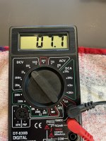
Finished the build and checking the DC balance. Hooked up with no power and get 0V.
I am assuming the amp needs to be connected to power to get 12 volts across the meter.
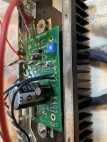
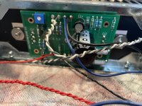
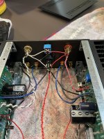
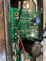
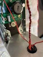
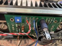
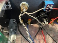
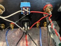
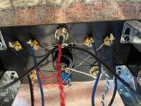
I need some help. I built two ACA's with the intention of using them as monoblocks. Neither is working. The first one registers when I try to set the potentiometer on one channel and the other is only reading 7.x Volts at max. I went back and resoldered the boards adding more solder to areas that looked like they may need a better connection. I traced all the wiring, and it looks correct. As this is my first project like this, I am unsure how to proceed. The lights do iluminate on both units, but i cannot get sound out of either.
I am hoping I did something obvious. Can someone please guide me how to troubleshoot.
Pics attached.
I am hoping I did something obvious. Can someone please guide me how to troubleshoot.
Pics attached.
Attachments
-
 IMG_1240.jpeg476.5 KB · Views: 77
 -
 IMG_1241.jpeg621 KB · Views: 84
 -
 IMG_1242.jpeg425 KB · Views: 81
 -
 IMG_1243.jpeg609 KB · Views: 67
 -
 IMG_1244.jpeg539 KB · Views: 77
 -
 IMG_1245.jpeg419.6 KB · Views: 66
 -
 IMG_1246.jpeg474.6 KB · Views: 63
 -
 IMG_1247.jpeg428.8 KB · Views: 69
 -
 IMG_1248.jpeg467 KB · Views: 66
 -
 IMG_1249.jpeg521.2 KB · Views: 79

- Home
- The diyAudio Store
- Amp Camp Amp Kit 1.6/1.8