The important voltage is the midpoint at the junction of the 0.47 and 0.68 ohm resistors.
I don't follow your readings, they show around 12v on Q2 source which is good but you then show Q1 source has 11.4v present. That should be ground (zero volts).
Don't overthink it.
Have you connected the speaker sockets correctly? Remember the ACA inverts and so the sockets are wired differently to how you expect. Red goes to ground and black goes to the amp output.
Make sure you haven't inadvertently added a short across the speaker socket by wiring them incorrectly. You should hear the speaker thump at switch on.
If the voltage on the PLUS end of the 3300uF cap is 12 volts and adjusts and if the FET's are hot then its probably all OK circuit wise and you have a simple wiring error in the speaker or inputs.
Measuring Resistor values once the board is packed.
ACA v1.8
I have a general question. R12 is 39K, once it is in a completed board should it still measure as 39K, or does the rest of the circuit, especially capacitors now make it impossible to measure the resistor in situ?
I think the value may be out, as in situ it is measuring as 20K.
This is my second DIY project and don't know all the basics yet. I imagine to measure it accurately now I will have to remove it from the board?
Thank you.
I'll add my two penneth here seeing as this was the day job for many many years and this scenario crops up on a daily basis.
Checking resistors in circuit is totally unreliable and not only because of surrounding interconnected components affecting the result.
The DVM type, its internal test voltage used for resistance measurement, the range you select and set and the polarity of the test leads all contribute to errors.
On the ACA, anything connected to the input (via R11) can also affect the result.
On a practical level if a low value resistor reads OK in circuit then it probably is so. If a higher value one does the same and reads exactly correct then it to is probably OK.
If you do not see the expected result then isolate one end and retest.
Thanks, I'll isolate and measure again, and will check the end to end resistance also. I had 39K on one channel, but 20K on the other, it is this discrepancy I did not like. Awaiting a better multimeter at the moment but will post my results when I get them.
I've found Step 56, so I'll check some voltages too.
I've found Step 56, so I'll check some voltages too.
Hi Mooly
I checked all connections for input and speakers and I had them wired correctly but I went ahead and reflowed it all to be sure. Also I found minor solder spatter between S & D of Q1 ( where S read 11v instead of 0v) it didn’t look even close to bridging the two but I scraped everything clean prior to powering up.
Let it warm, adjusted voltage and rechecked S on Q1, now it reads 9v instead of 0v. What would cause that?
Anyway I plugged in a preamp and CD player and fired it up. Didn’t hear the bump but did hear the caps charging so I hit play and it worked!
Should I be concerned about the voltage at S on Q1?
When I build my second one and it reads 0v on that one will they sound different from each other?
Thanks for your guidance. I’m feeling more confident about building #2.
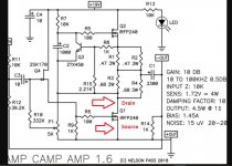
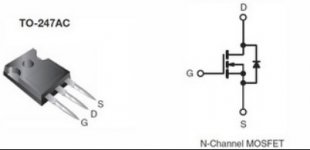
Q1 is the lower FET and the source should go to ground (zero volt line). I think you are mixing up the terminology here ") That point should always be zero volts, even if you have a fault or a short anywhere else.
That point should always be zero volts, even if you have a fault or a short anywhere else.
The middle lead of Q1 is the drain and that should be adjustable to either +9 or +12 volts depending on whether you are using an 18 or 24 volt power supply.
If it will not adjust then first question has to be whether the input FET (Q4, the 2SK170) is a genuine part.
If you can not achieve that 'half supply voltage' setting on the middle pin of Q1 then you have an issue, either Q4 is suspect if not genuine or you have a component error.
That point should always be zero volts, even if you have a fault or a short anywhere else.The middle lead of Q1 is the drain and that should be adjustable to either +9 or +12 volts depending on whether you are using an 18 or 24 volt power supply.
If it will not adjust then first question has to be whether the input FET (Q4, the 2SK170) is a genuine part.
If you can not achieve that 'half supply voltage' setting on the middle pin of Q1 then you have an issue, either Q4 is suspect if not genuine or you have a component error.
Thanks, I'll isolate and measure again, and will check the end to end resistance also. I had 39K on one channel, but 20K on the other, it is this discrepancy I did not like. Awaiting a better multimeter at the moment but will post my results when I get them.
I've found Step 56, so I'll check some voltages too.
Before you do anything else, make sure the rear switch is in the 'Central' position. If it is in either of the other positions you will have parallel connections between the 2 inputs...
The middle lead of Q1 is where I adjusted voltage.
And the middle lead is the Drain. You should be able to adjust this point above and below one half of the supply voltage you are using.
The lead marked S on the Q1troubleshooting photo indicates 0v. This is the lead that shows 9v not 0v on my white board.
I'm not familiar with that picture but yes, Q1 Source is definitely ground and 0 volts would be correct.
If you have 9 volts on that point then either you are measuring the wrong point of the connection is open circuit from FET to ground.
Am I still confused? Yes I am
You are not the only one
Attachments
... It’s my first DIY project so this is mostly foreign to an old man. Could someone share their wisdom and guidance to get this running? I’d really like to build the second one without as many issues.
Thanks So Much
A couple of things you can do to help us all understand 'where you are'.
1 Eliminate a shorted output. Measure the resistance from the red speaker terminal to the black speaker terminal, it should be 500 - 1000Ω.
2 Eliminate a shorted input. Measure the resistance of the RCA connectors from the inner pin to the outer gold ring. It should be about 49k to 50kΩ. (Rear switch in the central position.)
Then as Mooly says the voltage on Q1 source (S) is odd. Is your meter 'self ranging' and are you reading it correctly? Where have you placed the negative meter lead when you measure it?
Do Q1 and Q2 both get hot after 10 minutes being switched on?
Finally please post some good quality pictures of the boards and wiring so we can see what is going on.
Alan
 good luck.
ACA #2
I completed my second ACA 1.8 with no apparent mishaps. Let warm and adjusted voltage everything seemed to checkout. Plugged it into a preamp and CD player and turned in on. Heard the caps charge, hit play and only got right channel sound. Swapped inputs left for right. Still only had right channel sound.
Unplugged right channel and had some music and loud hum from left channel.
I stopped and checked resistance as suggested by Allan4411for my #1 ACA Build
left speaker lugs=1000 ohm.
Left RCA pin to lug=50.52 ohm
Right speaker lugs=1000ohm.
Right RCA pin to lug=50.22ohm
Also have continuity between between RCA leads and boards and speaker leads to boards.
One thing I noticed as being different from my #1 build is that when I put the 3 position switch down I get no sound at all while on my #1 build I still get sound in that position. Could that switch be suspected?
Any direction/advice is welcomed
It sounds like a wiring issue. Make sure you have not swapped input and ground to one of the input sockets.
------------------------------------------
Get the amp in the faulty state and then turn it off. Leave the input leads connected at the amp i.e. don't disturb anything at this point but disconnect the leads at the CD player end and leave them floating.
1/ Confirm that you have continuity between the two grounds of the two input RCA sockets. It should be almost as low a reading as you get just shorting the probes together.
2/ If that is OK then measure from ground of each input socket to the centre pin of each socket. It should read a 'high' resistance of at least 10k (the value of R11) but the exact value is an unknown due to the reasons I pointed out earlier.
So each input socket should read at least 10k from centre pin to outer ground.
3/ If that is OK then measure resistance from centre pin of each input socket to R11 of the appropriate channel. You should have near zero ohms (same as with probes shorted).
Speaker connections appear to be OK if you got hum and music while disconnecting the inputs.
- Home
- The diyAudio Store
- Amp Camp Amp Kit 1.6/1.8