Well, since the opamp is fed from the extremely clean regulated voltage, filtering its supply doesn't bring you anything. On the contrary, it introduces impedance in the supply line and you don't want that, it introduces load ripple on the opamp supply.
BTW Be careful with the '797. We never recommend the '797, not because it is bad; it's a great opamp, but it sometimes has a tendency to oscillate in these circuits.
Jan
BTW Be careful with the '797. We never recommend the '797, not because it is bad; it's a great opamp, but it sometimes has a tendency to oscillate in these circuits.
Jan
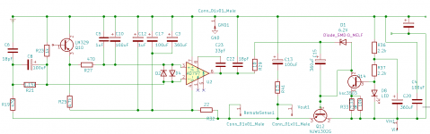
i realise that i can be difficult to implement AD797. If it works, i plan to compare it to other op amp, like opa1611 which doesnt need the compenstation capacitors and protection diodes , and has a reputation of being very resistant to oscillations. But in case i manage to force AD797 to work properly (<1R resistor to fine tune the output capacitor, additional decoupling). I put some place for extra components is there in case i can hear them, like 1uF stacked film instead of ceramic across the op amp, 100uF smd ceramic at the input or regulator, 1uF ceramic at the voltage reference input for opamp.
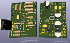
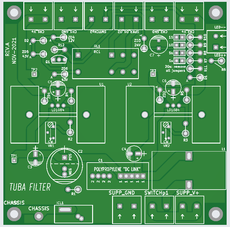
Took me a whole evening last night to optimize the pcb tracing and make pcb small, but to still have enough place for comfortable soldering of big components.
All signal paths and resistors at the bottom, most capacitors and ground plane on top, 63/43 mm, non inductive resistors in feedback path
How do you like it? :
Attachments
Last edited:
Well, since the opamp is fed from the extremely clean regulated voltage, filtering its supply doesn't bring you anything. On the contrary, it introduces impedance in the supply line and you don't want that, it introduces load ripple on the opamp supply.
BTW Be careful with the '797. We never recommend the '797, not because it is bad; it's a great opamp, but it sometimes has a tendency to oscillate in these circuits.
Jan
so you are saying, that if in my project, i just short the R32 resistor with wire and forget to solder additional caps, and pcb is just as good as original?
Does the R32 RC filter help in reducing oscillation risk with any op amp?
Attachments
Last edited:
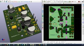
i realise that i can be difficult to implement AD797. If it works, i plan to compare it to other op amp, like opa1611 which doesnt need the compenstation capacitors and protection diodes , and has a reputation of being very resistant to oscillations. But in case i manage to force AD797 to work properly (<1R resistor to fine tune the output capacitor, additional decoupling). I put some place for extra components is there in case i can hear them, like 1uF stacked film instead of ceramic across the op amp, 100uF smd ceramic at the input or regulator, 1uF ceramic at the voltage reference input for opamp.
Took me a whole evening last night to optimize the pcb tracing and make pcb small, but to still have enough place for comfortable soldering of big components.
All signal paths and resistors at the bottom, most capacitors and ground plane on top, 63/43 mm, non inductive resistors in feedback path
How do you like it? :
Nice!
Jan
so you are saying, that if in my project, i just short the R32 resistor with wire and forget to solder additional caps, and pcb is just as good as original?
Yes.
Jan
For the Super Regulator "DC in", what's been referred to as "Raw DC", does this mean DC only after a rectifier? So this board takes in DC that's rectified but not smoothed?
There is a local decoupling cap at the input of the regulator. However, it is only small and for heavier loads it will be insufficient to provide a stable enough voltage. So in my opinion, the raw DC means a rectifier plus cap (>=1000 uF ).
For the Super Regulator "DC in", what's been referred to as "Raw DC", does this mean DC only after a rectifier? So this board takes in DC that's rectified but not smoothed?
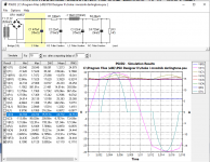
a man can say, that EVERY DC is RAW, but if you mean just the 100Hz from mains rectifier, then with certain CRCLCRC, i see a 20mV "ripple" at 6A current draw
Attachments
it`s first and foremost role is to stabilize a half-rectified raw dc to a true dc, so anyone can use it for this purpose only.
but it`s main task is in fact, to approximate ultra low impedance ideal voltage source, i.e. load independent.
kind of simulating, in my case, a 2x18Vx2.5A (90W) PSU, that has output impedance of a 4 Mega Watt power plant. it has measured output impedance in regions of 1uV, it means it would take a 1 000 000 Amperes to lower the rail voltage by 1Volt.
and i just want, that super regulator is focused mostly on following the musical load than had to handle additional and unnecessary high triangle waves from simple rectifier resevoir, and got something as smoothed as it is financilaly and technically feasible.
So the super regulator wants to see a smoothed DC?
Well, the input DC ('raw') should be a volt or so above the output at all times, otherwise it can't regulate, right?
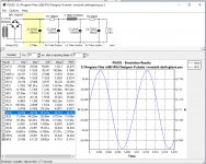
So if your output is 15V, the input should be say, for some extra headroom, minimum 17V at all times. So 18V DC with +/-1V ripple would meet that. And the ripple depends on the reservoir cap after the rectifier, and how much current you draw out of it.
Simulators are ideal to check this. Install Duncan's PSUDII.
Jan
i realise that i can be difficult to implement AD797. If it works, i plan to compare it to other op amp, like opa1611 which doesnt need the compenstation capacitors and protection diodes , and has a reputation of being very resistant to oscillations. But in case i manage to force AD797 to work properly (<1R resistor to fine tune the output capacitor, additional decoupling). I put some place for extra components is there in case i can hear them, like 1uF stacked film instead of ceramic across the op amp, 100uF smd ceramic at the input or regulator, 1uF ceramic at the voltage reference input for opamp.
Took me a whole evening last night to optimize the pcb tracing and make pcb small, but to still have enough place for comfortable soldering of big components.
All signal paths and resistors at the bottom, most capacitors and ground plane on top, 63/43 mm, non inductive resistors in feedback path
How do you like it? :
What improvements will you have with that ground plane? Any possible way to simulate ground planes in LTSpice?
The original SR design did use a ground plane and it was abandoned.
As ground planes are necessary and effective with very high frequency circuits, my guess is the ground plane was originally implemented in the SR for potentially oscillating chips, like the AD797.
Am I right, Jan?
Last edited:
Ground planes are great to battle mains hum. But the problem with ground planes is that it is very hard to control the ground current paths. So I abandoned it in favor of well defined ground return paths, making the supply cleaner. Mains hum can be easily avoided by other means like well defined wiring setup.
Jan
Jan
Could you say that ground planes are rarely necessary in audio circuits, which do not deal with very high frequencies? That's something that was said to me, by pcb designer years ago.
Separate ground returns, which can also become complicated to implement, seem like a more logical idea. I remember one DAC design of you, from TAA, where you did implement this principle, ending up with a multileg "spider" ground star.
Separate ground returns, which can also become complicated to implement, seem like a more logical idea. I remember one DAC design of you, from TAA, where you did implement this principle, ending up with a multileg "spider" ground star.
I, myself, always lay out a solid ground plane on the bottom copper layer. And I also flood/fill all unused regions of the top copper layer with ground. Here's an example; you can see that I routed exactly one non-Ground trace on the bottom copper layer. The rest is a solid plane. Click on the images to see them full size and undistorted.
Ground planes are good in most senses but you need a careful placement of parts for having optimum current paths. If you have multilayer boards, then it will become even more easier.Ground planes are great to battle mains hum. But the problem with ground planes is that it is very hard to control the ground current paths. So I abandoned it in favor of well defined ground return paths, making the supply cleaner. Mains hum can be easily avoided by other means like well defined wiring setup.
Jan
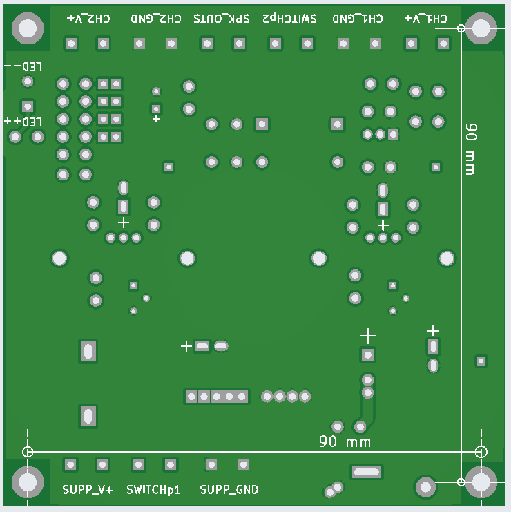
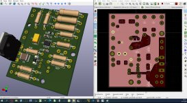
in my take of negative Super Regulator, i decided to make a Ground everything, that is not a signal.
Both upper and lower sides are mostly the ground.
symmetrical fields up/down pcb, are for the power transistors to avoid thermal deformation of pcb laminate (class A operation, 12W dissipation, 5V Offset, 2.5A Iq).
these few points that need back to Ground, are well spread around the ground pin middle-left
Attachments
Last edited:
- Home
- The diyAudio Store
- Super Regulator