The closer the primary and secondary are coupled, the higher the capacitance between them and the easier mains junk goes from prim to sec. If you use a xformer with separate bobbins, you will have less capacitance.
The problem is with separate bobbins that the transformer also becomes less efficient. That is why for power amps you almost always see a toroid, with tight coupling and good efficiency. Also, with the higher signal levels in a power amp, the mains junk coupling is less critical.
In preamps, DAC, that sort of thing, signal levels are (much) smaller so they are more sensitive to mains junk. Fortunately they also need less power so efficiency is not as important and separate bobbin xformers can be used.
The superreg has very good suppression of mains junk so it is less critical here.
Sorry I can't give any hard numbers because every case is different.
Jan
For those who are terrified of AC mains noise being coupled from transformer primary to secondary, why not include two transformers instead of one? The mains is connected to the primary of a (split bobbin) isolation transformer: 115V primary, 115V secondary (or 230/230 in Europe).
The 115V secondary of the isolation transformer is connected to the primary of your normal (split bobbin) power transformer: 115V primary, 18V (or your chosen value) secondary.
Now you get split bobbin goodness, squared. Mains junk is attenuated once in the split bobbin isolation transformer, and any residual that gets through is attenuated even further in the split bobbin power transformer.
Presto, for the small additional cost of USD 19.49 (sales link), you have synthesized a super-transformer, whose attenuation of AC mains noise is an order of magnitude better than ANY single transformer you can buy.
And, oh by the way, it attenuates both common-mode noise and differential-mode noise.
_
Last edited:
Is there a preferred type of power transformer for the rectifier circuit ?
I have read in a statement by John Curl that the typically wound Toroid is not good for low power circuits due to capacitive coupling of power line noise. Best to use R-core or EI core.
But what type EI core: split bobbin or the cheaper single bobbin?
Does it matter for the Superreg?
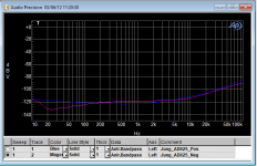
If you're worried about noise etc in the kHz to MHz range, by all means do NOT use the LM317 circuit in the new Texas Instruments data sheet. It's output impedance is measured in Ohms.
Super-Reg has prodigious PSRR (see chart below) and will cost less than an R-Core transformer. Mark's two-transformer idea will eliminate the nasties from DC on the mains!
Attachments
"Superreg" is a series regulator standard in the meantime and may be hard to improve.
I refer to the original circuit in https://linearaudio.nl/sites/linearaudio.net/files/superreg V2.3.pdf page 2.
Looking at the schematic the only obvious modification would be to supply LEDs D1 and D6
with constant current.
The supply pins of Operational Amplifiers U1 and U2 are "good enough" to be used as
constant current sources.
In order to do this required changes are :
- disconnect R2, R9, U1 pin 4 and U2 pin 7 from ground,
- connect R2 to pin 7 of U2,
- connect R9 to pin 4 of U1.
Check OP amp supply voltages, depending on type and current R2 and R9 probably have to be
decreased which is easily done by parallel resistors. Add supply pin capacitors when necessary.
The modification applies to symmetric plus / minus "super" regulators only.
Somebody with spare time may want to simulate or rewire and report ..
if i remember correctly, in one of 4 articles describing design and its caveats, authors stated that the D1/D6 diodes are a part of first CCS, that forces the regulator to start reliably. It may not start anymore after rewiring.
I have a question about capacitance values of C1, C2 and C3 - 100uF.
Can i insert a 360uF/35V cap (hybrid polymer 22mOhm ESR) instead ?
I have a question about capacitance values of C1, C2 and C3 - 100uF.
Can i insert a 360uF/35V cap (hybrid polymer 22mOhm ESR) instead ?
if i remember correctly, in one of 4 articles describing design and its caveats, authors stated that the D1/D6 diodes are a part of first CCS, that forces the regulator to start reliably. It may not start anymore after rewiring. ...
Yes, D1 and D6 are references for the respective current sources.
However the suggested modification is easy to try ..
Thinking about it yet another modification comes to mind, but a
drawing is required for this.
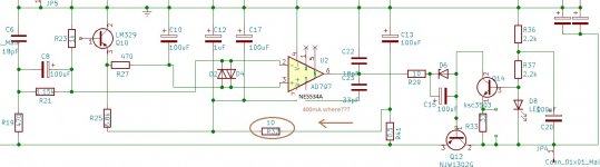
i have a persistent problem with negative voltage rail, it keeps giving me on 7.4 Volts instead of 17V
once i decoupled the oppamp psu with additional RC 10R 100uF tantalu + 1uF ceramic across, i see unexpected high dissipation on my R32 on schematic (10R), with too high 470mA current and little bit of smoke.
Funnily, without the voltage, the resistance of both legs of this transistors are some kR and rising. Where is this low impedance coming from ??
Could it be just soldering error ? Or if i is it the NE5534A that is soldered in NOW instead of AD797 ? the compensation capacitors at legs 8?
I have already resoldsered and measured both decoupling caps, and reversed the zener, no help. NE5534 a second one soldered with ESD care.
the positive rail with the same arrangement works fine.
Any ideas ?
Attachments
Last edited:
Exactely the same situation with lm336-5 in , same voltages round. this lm329 works fine outside the board.
I measured against ground around 8 legs, all seems i.O. (Brymen 896s with sharp needles). Decoupling 18pF and 33pF seem fine. (DER EE)
can it be the NE5534A Onsemi model itsefl ? Second one works just as the fist one, 7,4 Vout, high dissipation on 10R, smoke. caps shouldn do anything if unused..., positive rail works fine though!
pin 7 and 8 as usual connected, just covered with painted in actual model, shouldn`t have put it there, my mistake.
I have already resoldsered and measured both decoupling caps, and reversed the zener, no help. NE5534 a second one soldered with ESD care.
the positive rail with the same arrangement works fine.
Attachments
Last edited:
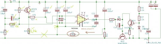
Pin 7 and 4 reversed, error current limited by R32
the same would happen on AD797 ?
Exactely the same situation with lm336-5 in , same voltages round. this lm329 works fine outside the board.
I measured against ground around 8 legs, all seems i.O. (Brymen 896s with sharp needles). Decoupling 18pF and 33pF seem fine. (DER EE)
can it be the NE5534A Onsemi model itsefl ? Second one works just as the fist one, 7,4 Vout, high dissipation on 10R, smoke. caps shouldn do anything if unused..., positive rail works fine though!
pin 7 and 8 as usual connected, just covered with painted in actual model, shouldn`t have put it there, my mistake.
I have already resoldsered and measured both decoupling caps, and reversed the zener, no help. NE5534 a second one soldered with ESD care.
the positive rail with the same arrangement works fine.
Did you look at my version of the Super regulator for JLH69?
https://www.diyaudio.com/forums/solid-state/3075-jlh-10-watt-class-amplifier-559.html#post5913289
https://www.diyaudio.com/forums/solid-state/3075-jlh-10-watt-class-amplifier-580.html#post6050539
yes, some year ago. I wanted to do it as good as possible, short straight SMDs, straight power connection on single 80x80 pcb. Everything went fine, JLH1969 measures well, positive rail has some ca 270kHz 5mV noise,
negative rail like stupid shows always 7,4V out, due to some "dark magic" involved here ;-)
negative rail like stupid shows always 7,4V out, due to some "dark magic" involved here ;-)
- Home
- The diyAudio Store
- Super Regulator