Hi,
Could I use an alternative of lm329 as reference? For example a 5v. Reference diode for a 12v output? On mouser the LM329 is quite more expensive than a common 5v.
Can I place before this regulator a bridge rectifier like this:?
DF005-G Comchip Technology | Mouser Espana
Thanks
Could I use an alternative of lm329 as reference? For example a 5v. Reference diode for a 12v output? On mouser the LM329 is quite more expensive than a common 5v.
Can I place before this regulator a bridge rectifier like this:?
DF005-G Comchip Technology | Mouser Espana
Thanks
")
Hi,
Which is the minimum power rating value for R6/R7? 1/10watt is too low?
How many ohms could approximate the R7 value to still have precise output voltage?
Ex: if R6 is 1k, R7 must be 740ohms to have a 12v output. 7/8 ohms of difference are too much?
Thanks
Which is the minimum power rating value for R6/R7? 1/10watt is too low?
How many ohms could approximate the R7 value to still have precise output voltage?
Ex: if R6 is 1k, R7 must be 740ohms to have a 12v output. 7/8 ohms of difference are too much?
Thanks
Last edited:
Hi,
Which is the minimum power rating value for R6/R7? 1/10watt is too low?
How many ohms could approximate the R7 value to still have precise output voltage?
Ex: if R6 is 1k, R7 must be 740ohms to have a 12v output. 7/8 ohms of difference are too much?
Thanks
How much precision do you need? Why?
You can do like this: measure the voltage and then calculate need resistor to connect in parallel with one of the feedback resistors. During the process you can try out the resistor just holding it with you fingers.
Last edited:
Hi,
Which is the minimum power rating value for R6/R7? 1/10watt is too low?
Thanks
Just calculate. Power in a resistor is (voltage across)^2 / resistance. With 15V and 2 x 1k, each resistor has 7.5V across, so the power dissipated is (7.5)^2 / 1000 = 0.056W, or 56mW.
These simple equations should really be in your mental toolkit if you are serious about diy. It is all at your fingers tips anyway with Google. I would hate to have to ask and wait for someone to answer everytime I wanted to know such things...
Jan
So:
Power dissipated in a resistor is voltage across X current through: P = V X I.
But from Mr. Ohm we also know that V = I X R or re-arranged, I = V / R. If you substitute this in the first equation you get P = V X V / R is V^2 / R.
In the above example we could also have calculated the current through the 1k with 7.5V across which of course is 7.5mA (0.0075A).
Then from the first equation we could calculate dissipation as P = 7.5 V X 0.0075 A = 0.0056 W.
Easy. Once you've done it a few dozen times it becomes 2nd nature and you do it from your head. ;-)
Jan
How many ohms could approximate the R7 value to still have precise output voltage?
Ex: if R6 is 1k, R7 must be 740ohms to have a 12v output. 7/8 ohms of difference are too much?
Thanks
Two factors: first is the exact reference voltage. Look up the accuracy of the LM329 (or whatever reference you use) in the datasheet and you will see that in general it is worse than a 1% resistor. So it is not worth while to sub-optimize the resistor values if the reference can vary more than the resistors.
Secondly, I wouldn't worry about the exact output voltage. 14.82V, 15.15V, what's the point?
But you can anyway calculate the ideal output voltage with different resistors. Assume a reference of 6.9V then 1k and 740R give you 1740 / 1000 X 6.9 = 12.006V. With 748 ohms it would be 1748 / 1000 = 12.0612 V. All moot, especially because the 6.9 V ref is not exactly 6.9 V, although I do recognize that knowing it exactly can be of personal interest.
Jan
Last edited:
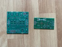
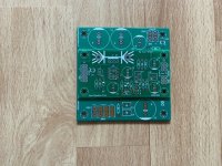
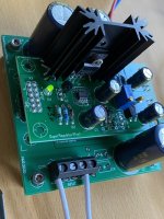
A couple of months ago I agreed to provide a voltage regulator PCB that offered all of the "Customer Features" requested by a Moderator here on diyAudio. To my surprise, one of the most urgent requests was to provide User Adjustable Output Voltage. The wise and crafty Mod knew, through long experience and hundreds of urgent Forum requests, that DIYers absolutely LOVE seeing their regulator output is exactly 15.000 volts on their 6.5 digit benchtop DMM. Whether necessary or not, apparent precision makes people feel very good about themselves. The Mod also knew, through experience, that DIYers would post a ceaseless, nonstop parade of urgent requests "How do I make the output voltage become 13.3 volts? What resistor values should I use? I am no good at math". Providing a 25-turn trimmer potentiometer on the PCB, eliminates these.
Other wise and crafty requests from the Mod included "rectifiers and filter caps on the regulator PCB" , "useable with either a dual secondary transformer (Toroid) OR a single secondary AC-to-AC wall wart" , "output current greater than ±1 ampere" , and "transformer snubbers on board". Which of these are solid engineering requirements, versus DIYer Delight Features, I will let each reader decide for herself.
That regulator can be found on diyAudio by searching for VRDN . It's certainly not a Super Regulator like Jan's here, but maybe it might be a pretty good regulator.
I have an issue (oscillating) with a Jung Didden superreg in combination with a Jfet buffer.
Oscillation stops when I remove ONLY the negative rail capacitor on from the buffer?? I don't understand why.
The superreg without the buffer is stable, I also used the 10R + 10n on the remote sense lines. (10n is on underside of trial/proto PCB)
I'm looking for some expertise, anybody willing to advise?
https://www.diyaudio.com/forums/analog-line-level/350773-discrete-buffers-4.html#post6319660
Have you tried this arrangement in comparison with a traditional 4-diode bridge, fast or any kind? Audible changes?
What are the advantages? Price probably is not.
I dont expect any audible change. I guess we all doing this for fun and self satisfaction. We are all human being at the end and we always want better and further.
Assume a reference of 6.9V then 1k and 740R give you 1740 / 1000 X 6.9 = 12.006V. With 748 ohms it would be 1748 / 1000 = 12.0612 V. All moot, especially because the 6.9 V ref is not exactly 6.9 V, although I do recognize that knowing it exactly can be of personal interest.
Jan
Hi,
I have some problems to do the right calculations, maybe someone can tell me where I do the mistake.
I follow this documentation to find the correct R13/14 value for obtain a 12v output.
Customizing the output voltage of the diyaudio store superreg project.
The output voltage is divided down by R14 and R13 for the inverting input. So if you want 10V output, R14 and R13 need to be selected so that this 10V is divided down to 6.9V at the inverting input. So there must be 6.9V across R14 and (10-6.9=3.1) across R13.
This give us a direct and simple equation: R13/R14=3.1/6.9. Assuming you select R14 first, then R13=(3.1/6.9)*R14. Like when you select R14=4.9k, then R13 needs to be (3.1/6.9)*4.9=2.2k. (You may need to play a bit with the R14 value so R13 comes out an existing value).
Let's say that I select R14=2.3k, doing the calculation R13=1.7k.
ex:
12-6.9=5.1
(5.1/6.9)*2.3=1.7k
BUT if I do 2300+1700=4000
4000 / 1000 X 6.9 = 27.6V ??????
I don't understand where I wrong...
thanks
Last edited:
- Home
- The diyAudio Store
- Super Regulator