This isn't what this thread is about, is it?
A couple of points can apply here.
1) You mention Mike Sulzer, have you contacted him?
2) A "Super Regulator" (SR) has generally become known as a regulator where the op amp rails are driven directly from the output. This isn't true for the circuit you posted.
3) You also have changed numerous parts from the BOM as listed in this thread. In particular, the higher BW parts for the pass device and the current source might be part of your problem. However, since I'm not an "official" of the thread principals, I'll defer here to Jan for further comment as to these deviations.
4) You have also changed the topology itself, in several regards. This will inevitably have the result of having the results reported being questioned. Apples go with other apples, oranges with oranges, etc.
5) As Jan has noted, dropping the op amp BW should help. Either by using a slower part (<10MHz BW), for example. Or, forcing an upper cap on op amp BW, with an RC network around the part in use. You can find an example of this within this link, Fig. 1, R15/C5. In this example, the values enforce a 10MHz BW. Note that this applies only for op amps that are unity gain stable! But in regulators I have built, both the AD825 and AD817 do show good stability, even with their fairly high BW.
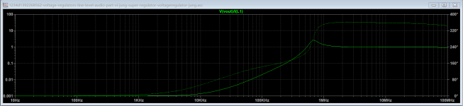
Have been playing with spice model for a sulzer style superreg; I did ac sweep with the current source load as the AC source, and plotted output voltage to see the load regulation.(not sure if it's correct, maybe the metaphysics probes are connected wrong, since its loop gain that should be shown here)
There is always a peak in the frequency response @ 2-5MHz, depending on the pass transistor used in simulation, and cannot be mitigated by tinkering with compensations like ESR Zero, bypass capacitor in the negative input of error amp. Using feedforward compensation caps at error amp even make this peak higheradding a small resistor to the emitter reduces this peak to ca. 6dB, at the cost of worsen performance at low frequency.
Could anyone kindly tell me where the problem is?
A couple of points can apply here.
1) You mention Mike Sulzer, have you contacted him?
2) A "Super Regulator" (SR) has generally become known as a regulator where the op amp rails are driven directly from the output. This isn't true for the circuit you posted.
3) You also have changed numerous parts from the BOM as listed in this thread. In particular, the higher BW parts for the pass device and the current source might be part of your problem. However, since I'm not an "official" of the thread principals, I'll defer here to Jan for further comment as to these deviations.
4) You have also changed the topology itself, in several regards. This will inevitably have the result of having the results reported being questioned. Apples go with other apples, oranges with oranges, etc.
5) As Jan has noted, dropping the op amp BW should help. Either by using a slower part (<10MHz BW), for example. Or, forcing an upper cap on op amp BW, with an RC network around the part in use. You can find an example of this within this link, Fig. 1, R15/C5. In this example, the values enforce a 10MHz BW. Note that this applies only for op amps that are unity gain stable! But in regulators I have built, both the AD825 and AD817 do show good stability, even with their fairly high BW.
Hello Mr. Jung,
1) No I didnt. Is Mr.Sulzer active in DIYA?
2) I am also aware that, by supplying the error amp and the Vref with regulated voltage from another regulator, the PSRR will pretty much at risk and the circuit itself is nowhere similar to your publication in 1995. Sorry if I am leading this post away again.
However, a Superreg with opamp rail supplied from regulated side seems to show "startup" problem in the simulation as well. By setting an initial voltage to the output capacitor it is possible to get a relatively meaningful result, but how much the simulation can compare to the reality in this case, is IMO
questionable.
Also, in some DIY posts it is mentioned that, the layout of supply trace to error amp has obvious effect over the stability. Combined with the post from Mark Johnson (about the positive feedback route from Vout to Opamp V+) I figured it is better to keep the whole design unsensitive towards layout technique.
3) 4) As Jan just mentioned, the error amp and the pass element shall have different BW in order to separate their phase shift from each other, will
gijve this a try. Personally I have already built some SRs according to the papers by linear audio and find the effects quite satisfying, did the simulations out of curiosity rather than blaming the original schematics
Walt's approach, powering both the error amplifier and the VREF generator from the superreg's final output node, is elegant. It is also efficient / low parts count / minimalist. It's beautiful!
But I personally prefer to use a few extra parts and a few extra sq.cm of PCB area, powering each of these from a locally filtered version of the superreg's input. It just makes me feel better. I'm not saying one is right and the other is wrong, or one is better and the other is worse. I merely have my own preference and, despite the extra cost which I happily acknowledge, that's how I choose to arrange my own circuits.
Same goes for startup / powerup. I prefer the higher parts count approaches. The beautiful and minimalist ones are probably perfectly fine, but they're not the ones I use.
It's DIY - do it however YOU want.
However, a Superreg with opamp rail supplied from regulated side seems to show "startup" problem in the simulation as well. By setting an initial voltage to the output capacitor it is possible to get a relatively meaningful result, but how much the simulation can compare to the reality in this case, is IMO questionable.
The simulation models may not model the startup accurately. In practice, there's no problem. I must have build a ton of them, never had starup problems.
Some people have recommended that the zener in series with the opamp output should be not bigger than Vreg-Vref, but I never considered that in my units.
Jan
Of course Jan, there is currently a pair of em running in my headamp, nothing gets cooked
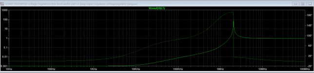
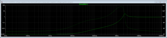
. My point is, if the sw cannot model the stable state of the SR with reasonable accuracy, it then doesnt make sense to do any research based on such a questionable model.Some results with LT1128 and several bjts coming with LTspice. The output Z also showed a peak, see attachments. That means instability?
BTW I send this sulzer style reg to one of my friends whos got Multisim, the "high impedance" range was even larger (with fzt857), rather than a peak it is now a whole moutain from 1MHz to over 100MHz...

Attachments
Of course Jan, there is currently a pair of em running in my headamp, nothing gets cooked
Some results with LT1128 and several bjts coming with LTspice. The output Z also showed a peak, see attachments. That means instability?
BTW I send this sulzer style reg to one of my friends whos got Multisim, the "high impedance" range was even larger (with fzt857), rather than a peak it is now a whole moutain from 1MHz to over 100MHz...
The problem is probably not the simulation software but the models of the opamps and other parts. Different simulators may use different models in their libraries that may not be fully accurate - they are models, not the real thing!
You can check that: simulate a circuit shown in a data sheet and see if you get the same graph as in the data sheet. Sometimes it is surprisingly accurate, sometimes not at all.
Especially start-up issues are frequent in all kinds of circuits, because models are not good at modelling that. Perfect startup simulation would require much more detailed modelling (and also some more refinement in simulation, that is true).
Some models are so-called macro-models that model behaviour rather than internals and they cannot be trusted in unusual situations like startup.
Some manufacturers have two types of models: very detailed and accurate ones but encrypted for own use, and behavioral ones for 'us out there'. Guess which are most accurate.
BTW Mike Sulzer set the whole superreg thing in motion but their have been numerous refinements and improvements over the years in particular by Walt Jung. It's OK to use a Sulzer circuit out of nostalgic considerations but there's much better out there.
Jan
Last edited:
Hello Mr. Jung,
1) No I didnt. Is Mr.Sulzer active in DIYA?
2) I am also aware that, by supplying the error amp and the Vref with regulated voltage from another regulator, the PSRR will pretty much at risk and the circuit itself is nowhere similar to your publication in 1995. Sorry if I am leading this post away again.
However, a Superreg with opamp rail supplied from regulated side seems to show "startup" problem in the simulation as well. By setting an initial voltage to the output capacitor it is possible to get a relatively meaningful result, but how much the simulation can compare to the reality in this case, is IMO
questionable.
Also, in some DIY posts it is mentioned that, the layout of supply trace to error amp has obvious effect over the stability. Combined with the post from Mark Johnson (about the positive feedback route from Vout to Opamp V+) I figured it is better to keep the whole design unsensitive towards layout technique.
3) 4) As Jan just mentioned, the error amp and the pass element shall have different BW in order to separate their phase shift from each other, will
gijve this a try. Personally I have already built some SRs according to the papers by linear audio and find the effects quite satisfying, did the simulations out of curiosity rather than blaming the original schematics
1 Ans) Not to my knowledge, unfortunately.
2 Ans) Yes, you certainly are leading people away from the virtuous features of a true SR.
But, whether you are totally aware of this or not, the circuit concoction you have shown still retains parts which are required within a true SR, but are totally redundant to the way you have things set up. You should clean up that circuit by deleting R4, R5, D1, D2, Q2 and C2. R6 should be retained in a practical value, as it has a stability impact. It has been part of the SR architecture for some time. You missed this, apparently. Drive the Q1 base directly from the op amp, through R6.
Yes, it is possible to see what appears to be startup "problems" with certain op amp SPICE models. Jan has explained this. and why. Do absorb that, fully.
Be aware that some actual op amps have phase reversal issues with applied CM voltage. i.e., TL071 and early JFET input related families. In the end, the real behavior is what the actual parts do, not the SPICE runs. At least one real world example of this has been published, back in 1997 such as this 5V regulator. Read the details describing the differences in line rejection with the op amp powered from the output vs. the input. And, very importantly, read "Kick-start me, please!".
Alas, it can't be really be determined here whether you have done anything positive towards the alleged layout induced instabilities, sans a PCB layout actually showing this.
Walt Jung
Hello,
I wanted to build a super regulator with 5 volts output, after post 535.
D2 LM4040AIZ - 5 / NOP
R5 2,5K
R2 5K
U1 AD817
D2 2 red LED serial
R6 bridge
R7 1K
Receive only 10 volts at 227R load resistor as output.
I wanted to build a super regulator with 5 volts output, after post 535.
D2 LM4040AIZ - 5 / NOP
R5 2,5K
R2 5K
U1 AD817
D2 2 red LED serial
R6 bridge
R7 1K
Receive only 10 volts at 227R load resistor as output.
Attachments
Hello,
I wanted to build a super regulator with 5 volts output, after post 535.
D2 LM4040AIZ - 5 / NOP
R5 2,5K
R2 5K
U1 AD817
D2 2 red LED serial
R6 bridge
R7 1K
Receive only 10 volts at 227R load resistor as output.
Dirk, we don't sit here normally with a reg schematic in front of us, so please post schematic so we can relate your values to it and advise a fix.
Jan
Is this it here, 2nd page: https://linearaudio.nl/sites/linearaudio.net/files/superreg%20V2.3.pdf
Post 529:
Post 531:
Post 535:
If someone could get a moderator or admin to insert into post 1 the values for 5 Volts, and maybe other Voltages, that might help people.
Post 529:
Hi...
I just ordered the super regulator boards...I will run one of them at 5 volts out.
From my readings...the voltage reference which is shown as lm329 or 6.9v should be changed to an lm 4040 2.5 volt reference.
Then there is d2 which is a 6.8v zener...It looks like this should be changed to a 2.5v zener or perhaps two red leds in series...
Do I understand correctly?...thanks
Post 531:
So, this is what I did: 5V in 5 moves
1) D5 & D10 LM4040AIZ-2.5/NOPB
2) R5 & R12 2.5 k
3) R2 & R9 5k
4) U1 & U2 AD817
5) D2 & D7 Replace with two red led in opposite direction of the zener in the schematic
According to my understanding the reasoning is the folloiwing:
1) To have a lower voltage reference
2) To have enought current through D5 and D10
3) To have enought current through D1 and D6
4) You need an opamp that can work with a single 5V rail
5) You need the output of the opamp to be around 3.1V as explained in post #498
I had to put a 10k resistor in parallel with R6 and R13 to get closer to 5V, otherwise I had 5.2 V.
Enjoy, Davide
Post 535:
Nothing wrong with your reasoning. I probably would have chosen a 4040-5 V ref, and bridge one of the feedback resistors, but that's just personal choice. Jan
If someone could get a moderator or admin to insert into post 1 the values for 5 Volts, and maybe other Voltages, that might help people.
Last edited:
Hello,
I wanted to build a super regulator with 5 volts output, after post 535.
D2 LM4040AIZ - 5 / NOP
R5 2,5K
R2 5K
U1 AD817
D2 2 red LED serial
R6 bridge
R7 1K
Receive only 10 volts at 227R load resistor as output.
R7, R6 set the output voltage, they scale the ref. If R6 is bridged and the ref is 5V, you expect 5V.
You just have to remember that the inputs of the opamp need to be the same, the ref voltage value. Everything else is just ohms law ;-)
In this case both should be 5V. Are they? And what is the opamp output?
Also, on your pic I see 2 LEDs for D1, NOT for D2. What is the D2 value? If over 5V zener, it won't work. Just use a single LED for D2, cathode towards opamp output.
There's no reason to fiddle with D1.
Jan
Last edited:
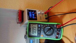
So this is good info. What do we see? The non-inv input is 5.5V, the reference. The inv input is 5.7, this is higher so we expect the opamp output to go down trying to bring the inv input to the same value as the non-inv input. And indeed that happens, output is as low as it can get with this opamp, less than a volt.
With the opamp output at 1V, and a LED in series with the output, the other side of the LED is expected to be roughly at 3V. That is connected to the base of the series transistor so we expect an output of say 2.4V. That is not the case.
That points to a LED the wrong way around. What is the voltage across the LED in series with the opamp output?
Jan
Red LED swapped and kathode controlled.
red led anode on pin 6 output opa 0v.
Kathode red led on pin 6 output opa 11.3 V
LED red anode on cathode measured 11.3V
Dirk
OK, so the LED was right way, with the opa output at 0V. Can you confirm that in that situation VLED anode = Vbase series transistor? What is the series transistor? Can you check it is correctly connected, collector to in input voltage?
What the opamp is doing is trying to pull the pass transistor base down, but not succeeding. Why?
Jan
anode led 2 opa output = 0V.
Q2 = BC556B.
Q2 Collector = Kathode Led2.
Q2= Emitter - Anode LED2 = 11,33V.
Q2= Bais - Anode LED2 =10,55V.
Q2= Collektor - Anode LED2 = 11,3V
Appendix Datasheet LED2.
D1= Grün 5V.
R2= 5K.
D2=Led Rot.
D5= LM4040AIZ 2,5V.
R7= 1K.
R6= Brücke.
R5= 2,5K.
Q3 = d4411
Dirk
Q2 = BC556B.
Q2 Collector = Kathode Led2.
Q2= Emitter - Anode LED2 = 11,33V.
Q2= Bais - Anode LED2 =10,55V.
Q2= Collektor - Anode LED2 = 11,3V
Appendix Datasheet LED2.
D1= Grün 5V.
R2= 5K.
D2=Led Rot.
D5= LM4040AIZ 2,5V.
R7= 1K.
R6= Brücke.
R5= 2,5K.
Q3 = d4411
Dirk
Attachments
Last edited:
If you are saying that the voltage across LED 2 is zero you have a connection problem. Its anode is connected to the base of the pass device through R3, right? Or maybe you made R3 10k instead of 10 ohms?
So what is the voltage on the base of the pass device? Probably 12V or so?
Jan
So what is the voltage on the base of the pass device? Probably 12V or so?
Jan
I have found a mistake.
Led 2 not soldered against the diode blocking direction, changed.
Q2 = emitter - anode LED 2,2V.
Bais - Anode LED 1.9V.
Collector - anode Led 2,3V.
R3 10R
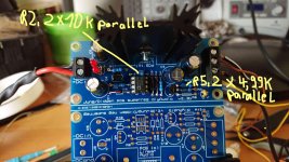
R2 changed to 10k original.
R5 changed to 4.99K original.
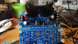
LED 1 + 2 now light up.
output 10,00V
Dirk
Led 2 not soldered against the diode blocking direction, changed.
Q2 = emitter - anode LED 2,2V.
Bais - Anode LED 1.9V.
Collector - anode Led 2,3V.
R3 10R
R2 changed to 10k original.
R5 changed to 4.99K original.
LED 1 + 2 now light up.
output 10,00V
Dirk
- Home
- The diyAudio Store
- Super Regulator