ADHV4702 has 170dB gain
LTC2058 has 150dB gain
ADA4522 has 145dB gain
CS3002 claims to have 300dB gain, typical.
")
But the GBW of those amps are quite small, so the bandwidth of the regulator could be much narrower?
Hello,
I have some problems with my superregs.
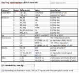
I used the pcb v2.3 of the diyAudio Store with the same BOM. I built 15v version.
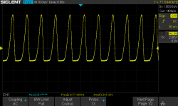
The output voltage is ok and handle input voltage variation (positive and negative reg) but I have noise/oscillation. Frequence and amplitude seem to increase with the load but not depend on the input voltage.
I used different voltage sources but there's no change. Positive and negative regs have the same problem.
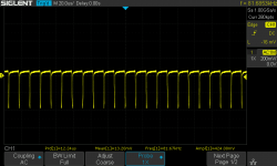
I joined a screen with 19v input and 100 mA load ( 150R ) (negative reg)
What should I check first ?
I have some problems with my superregs.
I used the pcb v2.3 of the diyAudio Store with the same BOM. I built 15v version.
The output voltage is ok and handle input voltage variation (positive and negative reg) but I have noise/oscillation. Frequence and amplitude seem to increase with the load but not depend on the input voltage.
I used different voltage sources but there's no change. Positive and negative regs have the same problem.
I joined a screen with 19v input and 100 mA load ( 150R ) (negative reg)
What should I check first ?
Attachments
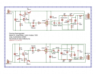
I used AD817 opamp. BC546C for negative and BC556B for positive. All others component are as the BOM.
I joined a screen capture*. The attached result was with 19v input and 100mA load (15v output)
I measure accross the load/resistor but I tried other point with same oscillations.
Oscillations are not visible in the source voltage alone with same load.
What do you mean by "I joined a screen with 19v input and 100 mA load ( 150R ) (negative reg)"?
I joined a screen capture*. The attached result was with 19v input and 100mA load (15v output)
I measure accross the load/resistor but I tried other point with same oscillations.
Oscillations are not visible in the source voltage alone with same load.
I used AD817 opamp. BC546C for negative and BC556B for positive. All others component are as the BOM.
I joined a screen capture*. The attached result was with 19v input and 100mA load (15v output)
I measure accross the load/resistor but I tried other point with same oscillations.
Oscillations are not visible in the source voltage alone with same load.
Ah yes, I should have known, you're French. Attached screen capture. I thought you 'joined' the wire screen to something. Sorry.
Try another opamp. Do you have an AD825?
Jan
Ah yes, I should have known, you're French.
I don't have AD825. I tried LT1028 and NE5534, both give the right output voltage (15v) but the same oscillations. Same oscillations with 2x9v battery.
Output voltage is 15v from 15,5v to 24v in input and the oscillations don't change with voltage.
I checked components orientation and value and it should be ok ( I don't see all resitors values).
I'm confused because I have the same issue in the positive and the negative reg.
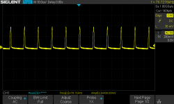
Yes that is weird, it points to some common stuff. Are you using a transformer with a center tap? If so, is the center tap connected to the two regulator ground points? Are output, ground and sense lines of each supply correctly connected?
On the screen shot you showed, it seems like negative pulses. Is that on the neg supply? How does it look on the pos supply?
What do you see at the opamp output pin?
Just thinking out loud what I would check.
Jan
Last edited:
I have stopped using transformer since I saw the issue. Now I check with a lab psu (or battery 2x9v ) one regulator at a time. I checked with an analog scope too. Allways the same oscillations.
I have 2 other superreg boards already populated (unfortunately with same parts). I just had to add the ref diode and the resistors to fix output voltage. I will test another one.
Thanks for your answers.
I have 2 other superreg boards already populated (unfortunately with same parts). I just had to add the ref diode and the resistors to fix output voltage. I will test another one.
Thanks for your answers.
I have stopped using transformer since I saw the issue. Now I check with a lab psu (or battery 2x9v ) one regulator at a time. I checked with an analog scope too. Allways the same oscillations.
I have 2 other superreg boards already populated (unfortunately with same parts). I just had to add the ref diode and the resistors to fix output voltage. I will test another one.
Thanks for your answers.
Can you do the measurements/questions I asked? Seems a pity to give up and build new ones, hoping they work different although they are the same ...
Jan
Sorry I missed your last questions.
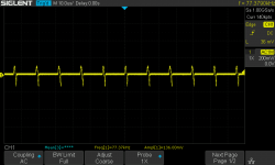
Yes it was the negative reg , I attached a picture of the positive reg (same as negative but inversed) and the opamp output (8v pikes ...). Pictures are from a test with 19v input (lab psu ) and 100ma load.
I saw something weird from the gnd in and gnd out (and then opamp -Vs) . I don't understand how it can be not flat.
I don't give up with this board I just want to see if the other have same issue to fix this one.
On the screen shot you showed, it seems like negative pulses. Is that on the neg supply? How does it look on the pos supply?
What do you see at the opamp output pin?
Yes it was the negative reg , I attached a picture of the positive reg (same as negative but inversed) and the opamp output (8v pikes ...). Pictures are from a test with 19v input (lab psu ) and 100ma load.
I saw something weird from the gnd in and gnd out (and then opamp -Vs) . I don't understand how it can be not flat.
I don't give up with this board I just want to see if the other have same issue to fix this one.
Attachments
Filter caps
Please forgive me if this has been covered. I didn't see it in my searches.
What do you like in terms of filter caps prior to the super regulator? Have you used a regulator prior to the super regulator? Have you done any listening tests with these configurations.
I've made two super regulators, in different applications - one in digital (positive only) and one for analog (both + and -). For the analog, I used a regulator prior to the super regulator. I didn't do any listening tests.
For the digital supply, I ended up with minimal filter caps. For this circuit, I listened to different configurations of the supply. I started with elaborate RLC filtering prior to the super regulator. Bypassing most of it sounded better to me, so that's where it ended up. (I felt it was more dynamic and free flowing without the extra filtering). I had assumed the digital circuit would benefit from the extra filtering and RF immunity.
Any experiences, recommendation?
Is it the same when you connect the meter leads together, measuring the lead resistance? Can you on this meter null the resistance when the leads are touching together?
Jan
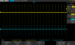
yes it's the same but I can't null the resistance. Actually I achieved 0.1 ohm by pressing harder.
but it's not my scope ! I can see the pikes growing from GndIn -> R2/-Vs (blue) -> GndOut (yellow)
Thanks you very much Jan. I'm affraid that I'm wasting your time, I will double check all this and I will come back.
Attachments
Last edited:
No worries, I am interested in this, naturally!
Let us know how it goes. Because it is on both regulators, it must be something systematic common to both. Right now I have no more ideas, but I will think about it.
Maybe one: if you shut of the neg regulator, remove the input, does the pos reg still have the oscillations?
Jan
Let us know how it goes. Because it is on both regulators, it must be something systematic common to both. Right now I have no more ideas, but I will think about it.
Maybe one: if you shut of the neg regulator, remove the input, does the pos reg still have the oscillations?
Jan

I found my mistake. I used 100nF instead of 100pF for C11 / C12. I removed it and there's no more oscillation. I tried some values to confirm and indeed big values make trouble...
Sorry for that. Thanks for your help.
Good idea to read Walt Jung's original 1995 articles in which he describes the perils of "capacitor rolling" -- the impedance of the SR is spectacularly low and requires the ESR of an aluminum electrolytic on the output. Local decoupling with ceramics near the final destination are OK as the resistance of PCB traces or wires raises the impedance.
The WJ articles are archived all over the web.
- Home
- The diyAudio Store
- Super Regulator