The dynamic response of the power supply is determined by the gain of the pass transistor and the speed of the error amplifier.
Low noise is nice, but .... well it's like the dog-food problem in linear programming.
Agree, but when you have a good local decoupling at the load, the dynamic response of the regulator becomes less important because the load bypass will source step load changes.
And also, don't forget that measuring step load changes with 1uS fast pulses provides nice (or not) pictures but is, for analog audio, irrelevant. How fast you think a 'step response' is for a full scale 20kHz signal?
It may be different however for a digital load like a DAC, but here the local decoupling gets even more important.
The art of electronics is to balance a host of often conflicting and interacting parameters, NOT to get hung up on a single issue.
Jan
So according to that, and if the relationship between Zout and transient response is as stated, whichever that Jung reg is, blows the rest away!
With the caviat that it needs 100mA drawn from it?
And that was not the one in this thread but the older type with preceded with the three pin regulator.
But the Jung/Didden V2.3 in this thread is even better?
... measuring step load changes with 1uS fast pulses provides nice (or not) pictures but is, for analog audio, irrelevant. How fast you think a 'step response' is for a full scale 20kHz signal?
Many designers build in a "margin of safety" in the frequency response of their equipment, to help ensure good performance at the highest audio frequencies. For example, the standard rule-of-thumb for slew rate is: "One volt per microsecond, per volt of signal swing" which you can key into your very own pocket calculator and find that it corresponds to slewrate limiting at 160 kHz. This aspect of the audio circuit design is deliberately chosen to operate correctly all the way up to 155 kHz inputs and outputs.
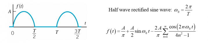
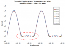
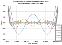
The standard argument for higher bandwidth power supplies is: they do NOT supply pure sinusoids of output current. Instead, thanks to push-pull amplifier circuits and dual rail supplies, the power supply provides half-sinusoids. Unlike sinuoids, the frequency spectrum of a half-sinusoid extends to infinity; Fourier series summation shown in attachment 1 below.
When a push-pull amplifier delivers a 20 kHz sinewave, the power supply current has harmonics that extend well beyond 20 kHz. I have plotted them below. I plotted (a) only the fundamental plus the first harmonic; (b) only the fundamental plus the first two harmonics; (c) only the fundamental plus the first three harmonics, ... , (j) fundamental plus the first ten harmonics. As you can see, to accurately deliver the desired half-sinusoid, you need AT LEAST the first seven harmonics. Seven gives a reduced-ugliness output but not a pure output.
So, I recommend you test your power supplies with sinusoidal loads at frequencies AT LEAST as high as 140 kHz. Using the bandwidth-risetime equivalency formula, that corresponds to a step function of current (a/k/a square wave) with a risetime of 2.4 microseconds or less.
See you later today at BAF!
Attachments
My experience has been that each capacitor, or combination of, produces different, or very different sonic results.when you have a good local decoupling at the load, the dynamic response of the regulator becomes less important because the load bypass will source step load changes.
I 'tuned' a few DACs in recent years, and my 'The Wire' headphone amp, with a bank a polymer caps and a black gate, combinations of polyprop and polystyrene. Over months of running in the caps and a testing it took a lot of evenings of critical listening on several systems to decide what sounded the best compromise on each DAC and system.
That's a mess really, and whilst applied with scientific method, is not really science, more art.
So I was hoping that a method better than selecting capacitors would produce a better effect, even across the audio band, rather that with a few peaks of clarity or emphasis and other peaks of dullness or mush or glare or boomyness.
Last edited:
Speaking of harmonics ==i've posted this before -- at the suggestion of one of the Linear Audio correspondents I ran an FFT of the output of several regulators with a 1kHz signal coupled to the output. to see the distortion they place on the power supply rails. The Jung and Sjostrom came out quite nicely and they are somewhat similar designs.
The Burson regulator came out pretty poorly in testing, but sounded wonderful. For that reason Jan decided to call it "euphonic".
Jung SR below:
The Burson regulator came out pretty poorly in testing, but sounded wonderful. For that reason Jan decided to call it "euphonic".
Jung SR below:
Attachments
I would to share my findings and ask for advice. I built the Amb σ22 power supply.
The σ22 regulated power supply
When I compared it to the stock SMPS in my mixer, the linear AMB subjectively sounded slower and less dynamic with softened transient responce.
Why is that? I expected the linear supply to sound better.
Is the superreg have chance of sounding more dynamic?
The σ22 regulated power supply
When I compared it to the stock SMPS in my mixer, the linear AMB subjectively sounded slower and less dynamic with softened transient responce.
Why is that? I expected the linear supply to sound better.
Is the superreg have chance of sounding more dynamic?
Can I be permitted another really basic question regarding +/- supplies? I'm almost too embarrassed to ask but...
If one needed a supply of, for example (just to pick a round number), 0.5A RMS. Is that load split across the each of the + and - boards or 0.5A (0.7A peak) for each? I'm looking at heat dissipation and wouldn't want to be a factor of 2 out.
If one needed a supply of, for example (just to pick a round number), 0.5A RMS. Is that load split across the each of the + and - boards or 0.5A (0.7A peak) for each? I'm looking at heat dissipation and wouldn't want to be a factor of 2 out.
a dual polarity supply can supply current from either pole.
The load may return some or all of this current via the Zero Volts line.
But many loads actually send nothing back via Zero Volts.
The current flows out of one pole and returns via the other pole.
i.e. Power = I*{Vcc+Vee}
The load may return some or all of this current via the Zero Volts line.
But many loads actually send nothing back via Zero Volts.
The current flows out of one pole and returns via the other pole.
i.e. Power = I*{Vcc+Vee}
Andrew thanks for the response. I'm still thinking of a headphone amp supplied by +/- 12V and the heat dissipation of the pass transistor. I think I should be looking at a sinusoidal load (plus some bias component) and hence the load is split across the two pass transistors but as this is the first time I've looked at this I don't want to make the mistake given the magnitude of error if I do.
Last edited:
Look at the current passing one series regulator.
With no load current, the I is constant.
You can calculate dissipation in the pass transistor from I*Vdrop
When the output is passing audio current, then the I through the pass transistor is not constant.
Dissipation is more complicated.
Does the current turn off as in a ClassAB output stage or does it vary by an equal amount either side of the quiescent value (ClassA), or does it do something in between those two limiting conditions?
A DMM measuring average voltage across a current monitoring resistor will give the wrong answer. But it is close enough for most of us to size the heatsink.
If it's a DIY project and not a commercial product that has to compete with other commercial products on (price-to-performance ratio), just use Brute Force and Massive Overkill.
Thus you need a bipolar power supply that provides at least 0.6A to drive the lowest-imaginable-impedance headphones (16R). At that headphone impedance the bipolar supply voltage needs to be at least ±17 volts. On the other hand if your headphones are 250 ohms impedance, and if you want to pump 3 Watts into them (!), your bipolar supplies need to be at least ±34 volts {proof left as an exercise for the reader}.
Don't forget to account for mains sag, transformer loss, diode bridge voltage drop, CRC voltage drop, and max ripple.
- Assume 3 Watts into 16 ohms (!)
- Assume 7V across output pullup and 7V across output pulldown: MaxVout = V+rail - 7V
- Assume 15% efficiency: Pout = 0.15 * Pin
- IoutRMS = sqrt(3W / 16ohms) = 0.43A
- IoutPeak = sqrt(2) * 0.43 = 0.61A
- VoutRMS = sqrt(16ohms * 3W) = 6.93V
- VoutPeak = sqrt(2) * 6.93 = 9.80V
- Vsupply+ = 7V + 9.80V = 17 volts
- Vsupply- = -7V + -9.80V = -17 volts
- Pin = (3W / 0.15) = 20 watts
- Pin = Isupply * Vsupply, therefore
- Isupply = (20W / (17V+17V)) = 0.588A
Thus you need a bipolar power supply that provides at least 0.6A to drive the lowest-imaginable-impedance headphones (16R). At that headphone impedance the bipolar supply voltage needs to be at least ±17 volts. On the other hand if your headphones are 250 ohms impedance, and if you want to pump 3 Watts into them (!), your bipolar supplies need to be at least ±34 volts {proof left as an exercise for the reader}.
Don't forget to account for mains sag, transformer loss, diode bridge voltage drop, CRC voltage drop, and max ripple.
Thanks. I very stupidly forgot everything I had read regarding audio amplifiers and then posted a very dumb question as a result. Sorry.
The maximum current the output buffers (LME49610) of the Wire BAL-BAL can provide is 250mA. There's a pair per channel and obviously two channels. So even if both channels were driven to maximum that's 0.5A. There's also about 80mA or so of quiescent current (depending on rail voltages) plus losses in supply itself (bleeder resistors etc).
I don't think I need rail voltages above +-12V (well below the +-22V max of the LME49610). Even relatively low sensitivity cans, e.g. 85dBSPL@1mW with impedance of 18 Ohms need less than 11V to hit the threshold of pain which I have no interest experiencing intentionally. The 18 Ohm impedance headphones I'd like to own have a significantly greater efficiency and other cans I might covet with lower efficiency have a much friendlier impedance.
My supply can handle a LOT more than 0.6A and even at those current levels the thermals are readily manageable (and even above) as I will simply bolt the pass transistor (and rectifier diodes) to the base of the chassis as that's the way my existing boards are configured anyway. Apart from the quiescent current both + and - pass transistors aren't passing current at the same time.
I'll ensure my transformer secondaries supply enough headroom voltage for the regs at the low end of mains supply. A quick look suggests 15V secondaries to ensure 5V of Vin-Vout differential at the low end of the mains. Obviously the headroom and dissipation will be higher at the high end of mains supply but should still be okay. I should oversize the transformer so something between 30VA and 50VA should be more than excessive.
I just need to think about capacitors for the supply input filters of the reg boards (10mm pitch). Those I used for my last project (Mundorf Lytic AG) are likely excessive (plus they're expensive). The range of electrolytics out there is bewildering. Anyone have a favourite brand and series for this sort of application which they'd care to recommend?
With the wire Bal-Bal, for each channel, both LME49610s conduct the current at the same time, because it's 'balanced', there are two amplifiers in parallel, but with a common supply. The current path is from, eg, the +ve capacitor plate, to one LME49610, to the voice coil, to the other LME49610, to the -ve capacitor plate.
I've not yet tried various regulators with the Bal-Bal, but with the three transistor discrete I have there now, when it fed my CD player DAC and output chips, every different transformer I used changed the sound from the speakers, and not by a small amount. I have 50,000uF or so on there and it just got better and better the more I added, and they're all decent types, Black Gates, Nichicon KZ, Oscon, Polymer.
Despite what some people say about local decoupling on that headphone amp, it's clearly not that simple (with my existing reg) as I added 4 x 100uF black gates across the 4 x supplied polymers already on there, and got a load more bass (louder and more transient, just the same as Black Gates always do).
So, I'm going to have to try a few other regulators, starting with the subject of this thread, to hear for myself if any do confer immunity to the pre-regulator components, which will be a boon as I have a bespoke made for me 100VA on a 300VA M0 core toroid feeding a big board of expensive caps taking up space that I could free up.
I'm hoping a decent regulator, direct onto the pins of the LME49610s, will do better than the local banks of Black Gates and polymers.
And sorry to all reading this that I haven't done it already and reported back and we're suddenly(!) on post 713!
Last edited:
Found this interesting statement regarding regulators:
"Liner regulators hold the voltage stable and have low output impedance up to a maximum of 20 KHz for very good regulators. Beyond this, the internal resistance of the regulator rises. In addition, the problem of Ground Bounce results due to the phenomenon of constant voltage. This means that the current varies according to the load and change of signal. This change of current results in the change of voltage at signal ground which in turn acts as interference to the passing analog signal. This effect especially the circuits with high gain (Phono). The advantage of our cross regulator is that the current is held at a constant level. Therefore it produces less interference at the signal ground. The tone is much more clear. Comparative tests have confirmed this result."
Can anyone share their knowledge on voltage vs. current regulators?
Is the superreg performing current regulation or just voltage regulation?
Sure:
TECHNOLOGY - Crayon-Audio
look in the "Power regulator for the small signal amplifier" paragraph.
TECHNOLOGY - Crayon-Audio
look in the "Power regulator for the small signal amplifier" paragraph.
Agreed . Crayon use of the term "current compensated chokes" reinforces the hype view. Choke are a passive current change resisting device that stores energy . to call it current compensated is ok but a clear sign that the marketing department is at work fluffing up the standard features of passive part trying to make it special when they all do the same thing. Well at least that is the way it looks to me.I feel that the text is marketing BS. You have (or could have) ground bounces in digital circuits for sure but hardly in analog low level circuits.
The super regulator is a voltage regulator.
I'm not sure where I went wrong, when I have the power supply hooked up to my Ba-3 front end the power supply was shorting out and the light bulb tester would light up I rewired the supply to the preamp and it was working but had a loud hum, then it started shoring out again. When I unhook the supply board from the preamp it works fine. Did I ruin a op amp or regulator?
Last edited:
- Home
- The diyAudio Store
- Super Regulator