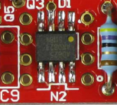
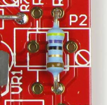
After blowing out several SSM2019 opamps, (the successor to the SSM2017 which WJ used in his 1995 noise measurement setup) I finally called ADI and asked them what the deal was with the protection diodes -- basically they can't handle a lot of stress.
The LME49710 gave nice results, but it's input doesn't appear to be protected.
I ordered several sets of the boards. Will contribute the unused OCS ones to the DIYAUDIO museum if and when it gets constructed --
The LME49710 gave nice results, but it's input doesn't appear to be protected.
I ordered several sets of the boards. Will contribute the unused OCS ones to the DIYAUDIO museum if and when it gets constructed --
you should change ... the D5/D10 series resistor to get the current through them back to about 1.5 to 2 mA.
Jan
Looking for clarity here. Is this to keep the diodes from needing a heat sink, because this current doesn't come close to the .25watt rating of the resistors or the max current rating of the diodes.
Additional question
Why not using a Pot to fine adjust the output voltage ?
Thanks,
regards
Marcus
Two reasons, or maybe even three:
1 - The exact output voltage is unimportant; 14.8V or 15.15, who cares;
2- Such a pot would be the most unreliable part in the whole unit, especially when it gets older and is exposed to atmospheric dirt;
3 - Cost money and PCB real-estate for no advantage.
No, I don't like pots a lot
Jan
BTW Mark (Variac) just pointed out to me that one of my favorites for the error amp, the AD825, is no longer available in DIP case, only in SOIC SMD. Bummer!
I should hang on to the few I have left. But I also have some of those SOIC to DIP adapter boards, which can also come in handy here.
Jan
I should hang on to the few I have left. But I also have some of those SOIC to DIP adapter boards, which can also come in handy here.
Jan
Really, is there any place we can find through hole AD825? My initial search did not show anything but smd.
So, if the regulator is rated at 1A, I assume this means one could build a nice, little 4W per channel stereo amplifier. And maybe compare it to an identical amp, using a passive power supply instead.
For nearfield listening, I assume it would be superb.
So, if the regulator is rated at 1A, I assume this means one could build a nice, little 4W per channel stereo amplifier. And maybe compare it to an identical amp, using a passive power supply instead.
For nearfield listening, I assume it would be superb.
Really, is there any place we can find through hole AD825? My initial search did not show anything but smd.
So, if the regulator is rated at 1A, I assume this means one could build a nice, little 4W per channel stereo amplifier. And maybe compare it to an identical amp, using a passive power supply instead.
For nearfield listening, I assume it would be superb.
Yeah I can't find them either, but I have redesigned the board for both DIL and SOIC. I'll check with Jason if he has already boards made with only the DIL.
Anyway there are enough other good opamps that still are available in DIL.
About the rating: someone asked how much current and I said probably an amp or so with some measures like sufficient heatsink etc. That's not an official 1A rating. Since this is diy I guess many people will adapt it to their own requirements and know how to do it or ask.
Jan
The AD825 DIL08 has been gone for at least 10 years.Really, is there any place we can find through hole AD825? My initial search did not show anything but smd.
For example, I see that AD825 has 50mA minimum output current capability. D45H11 has a minimum hfe of 40 as I recall, which means that you can have 2A output.
Assuming this 2A is peak value, you could have 1.41 A rms, which is 16 Watts of power for a 8 ohm load.
Combined with the +/-15V maximum power supply of the AD825, it is possible to easily make a 25V supply per rail.
So, you can build two super regulator supplies, each one about +/-14V, feeding two DC coupled power amplifier stages. Combined with the 1.41 A rms rating calculated above, this means it would be possible to construct a stereo, 15W per channel power amplifier.
Not bad at all, I think.
This would mean you would need reliable heatsinking, of course. But a heatsink of 3C/W, would mean that if each pass transistor dissipates around 8 watts at most, temperature would rise about 24C. A 2C/W would improve this.
So, for small rooms, I think you can get a superbly regulated power amp. And then compare it to a power amp having a simple, good reservoir that would be cheaper too - and see if there is any difference.
EDIT: Thanks for the double confirmation of the AD825's lack of DIL availability.
Last edited:
Sziklai
Hi,
Us a Sziklai as pass transistor. For exmple Q1 BD441 npn and Q2 MJE15031 pnp, It lowers the noise and distorsion, just the feedback from Q2 to Q1,
And use a resistor of 100 Ohm between the base of Q1 and the emittor of Q2
This transistor will too increase a capasitor multyplayer, here is no resistor of 100
Ohm necessarry.
Zjaakco
Yes, it is hot. By the way, rms (thus, heating) value would be around 35mA. Still hotter than ordinary.
Why not "tap" (tightly enough to take away heat, but not squash the IC) a 1cm aluminum rectangular bar on the opamps? A bit of creativity and job done, I suppose.
Yes and yo can also get self-sticking mini heatsinks for opamps.
BTW Instead of the AD825 you can use the LME49710, which is also quite fast and even lower noise. The slew rate is less but that's irrelevant as the opamp output is basically moving only a few dozen mV in operation anyway.
The DIP version is relatively low cost.
Jan
Yes, it is hot. By the way, rms (thus, heating) value would be around 35mA. Still hotter than ordinary.
Why not "tap" (tightly enough to take away heat, but not squash the IC) a 1cm aluminum rectangular bar on the opamps? A bit of creativity and job done, I suppose.
That can be improved by modifying the output series zener so that the output is only a few volts below the supply. At 3V below and 35mA that's just 100mW. Not too hot.
Jan
Last edited:
Two reasons, or maybe even three:
1 - The exact output voltage is unimportant; 14.8V or 15.15, who cares;
2- Such a pot would be the most unreliable part in the whole unit, especially when it gets older and is exposed to atmospheric dirt;
3 - Cost money and PCB real-estate for no advantage.
No, I don't like pots a lot
Jan
Thank you for explanation, you have convinced me
1 In most cases absolute voltage is of no importance ... but.... it feels better with an exact voltage.... (with an uncalibrated voltmeter)Two reasons, or maybe even three:
1 - The exact output voltage is unimportant; 14.8V or 15.15, who cares;
2- Such a pot would be the most unreliable part in the whole unit, especially when it gets older and is exposed to atmospheric dirt;
3 - Cost money and PCB real-estate for no advantage.
No, I don't like pots a lot
Jan
2 To my experience a trimpot is rather reliable in industrial environment and even better in home enviroment. Electrolytic caps is the worst part.
3 Yes, but not much and takes some space but you can do as I do, resistors and a pot in the same spot. I might add that I also avoid trim pots.
Attachments
What I did in my implementation of Sulzer's reg is to simply provide two parallel resistors instead of one for the unbypassed portion of the output divider.
Thus, you can actually fine-tune the voltage up to a sufficient degree. Escpecially if you measure the reference voltage beforehand.
For instance, I had an LM329 having a value of 6.83V. I decided to put a 3.3k resistor in parallel with the bypass feedback cap, and use a parallel combination of 10k//200k for the second, unbypassed portion. Aiming at roughly 9.2V.
The result? 9.2V
You can always buy a dozen of each resistor value and measure combinations that can bring you even closer. To me, making the down leg 2 resistors instead of 1, satisfies trimming accuracy in a cheap and clean way. Additional space is also only 1 resistor more - solder it vertical (or directly on the existing resistor ), and there you go, you control your digits and hardly see it.
EDIT: On another build, I had 7.09V reference and decided to go close to 9.05V for output. 3.3k again for the upper leg, 16k//47k for the lower leg. Done! It requires a very simple calculation, brings you really close to where you want, and costs almost nothing.
Thus, you can actually fine-tune the voltage up to a sufficient degree. Escpecially if you measure the reference voltage beforehand.
For instance, I had an LM329 having a value of 6.83V. I decided to put a 3.3k resistor in parallel with the bypass feedback cap, and use a parallel combination of 10k//200k for the second, unbypassed portion. Aiming at roughly 9.2V.
The result? 9.2V
You can always buy a dozen of each resistor value and measure combinations that can bring you even closer. To me, making the down leg 2 resistors instead of 1, satisfies trimming accuracy in a cheap and clean way. Additional space is also only 1 resistor more - solder it vertical (or directly on the existing resistor
EDIT: On another build, I had 7.09V reference and decided to go close to 9.05V for output. 3.3k again for the upper leg, 16k//47k for the lower leg. Done! It requires a very simple calculation, brings you really close to where you want, and costs almost nothing.
Last edited:
- Home
- The diyAudio Store
- Super Regulator

