I would prefer that both references have almost the same voltages. Which LED did you use? Did you check that the reg oscillates? Try replacing R17 and R19 with 1K and increase the current through the reference. A long time ago, I made four such references and the differences were in tens of mV.To quote personal messages probably not very nice but want to share finished and working project ant to thank you all for helpful advices. My reference voltages from GLED431 slightly off, at the positive rail 6.7V and at the negative 6.85V and leds on negative rail are a little bit lighter. But I put trimmers to have a possibility to adjust output voltage and I can set exactly 15V. Should I worry about these reference voltages?
View attachment 1289258
Attachments
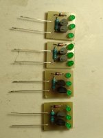
Yes, it was my fault. I already noticed that. Just put a wrong resistor (instead of 390R I put 1k and opposite for another one). Now everything is fine. LED’s are from old stock green SMD and I do not remember exactly the type. But voltage drop across one is about 1.8V. So, chain is from 3 leds and one 1N4148 diode.
Looks like I was happy too earlyI would prefer that both references have almost the same voltages. Which LED did you use? Did you check that the reg oscillates? Try replacing R17 and R19 with 1K and increase the current through the reference. A long time ago, I made four such references and the differences were in tens of mV.

On my scope the picture is not very pleasant:
c11/c12 caps are correct. What else can cause problems?
That's what I was afraid of.Looks like I was happy too early
On my scope the picture is not very pleasant:
To begin with, put a small electrolyte or film parallel to the reference. Increase the value of C10 and C18(or put a small electrolyte in parallel). What type of tantal are you using? Also measure Vds on BSS169, I've never worked with those mosfets so I'm interested in those voltages.
As for the PCB, I would like it to be more compact and the lengths of the lines to be as short as possible especially around the op amp.
Thank you, grunf, things are worse than I thought. With GLED431 probably everything is ok. Before I assembled it on PCB I tested it on test board and tweaked resistors to get 6.9V. I will measure voltages around current source transistors and will post it later. But now I tried more simpler things. First of all I disconnected GLED431 current source with BSS169 mosfets and replaced it by 1.2K resistor to set current for GLED431 to about 6.7mA. Oscillation gets worse. Then I replaced GLED431 with an original LM329 voltage reference. And now oscillation at 2MHz frequency but it worse than before:

My tantalum capacitors are from Farnell:
https://lt.farnell.com/kemet/t491x107k025at/cap-100-f-25v-10/dp/2321230
And for now I am not able to do symmetrical changes on -15V rail because had only one LM329. My power supply is loaded with a phono preamp and I made the mistake of not foreseeing an option to disconnect it from power supply. A simple 0R resistor would have solved a problem. If I disconnecting -15V rail things are changing and I do not see this very clear 2MHz oscillation just some garbage as on GND plane. My first thoughts were that PCB layout is bad but now I cautiously thinking that maybe oscillation on -15V rail might have an effect to +15V rail. Or with half of power load is changed. But maybe not. So, will try to do the same procedure with negative rail but need another LM329
But any suggestions would be greatly appreciated.
And for now, I would like to congratulate everyone on the upcoming Easter 🐣
Some update:
As suggested changed C10/C18 from 0.1uF to 1.0uF and on negative rail removed GLED431 constant current source with Mosfets and instead added 1.2k resistor to supply 6.7mA current. So, positive rail with LM329 and negative with GLED431 and looks like oscillation gone. I only detecting the same signal as on ground plane:

Understand that GND should be plain line but with such small signals and antique equipment and probably measurement technique I am getting such weird results. But anyway, prime suspect probably is GLED431 constant current source.
As suggested changed C10/C18 from 0.1uF to 1.0uF and on negative rail removed GLED431 constant current source with Mosfets and instead added 1.2k resistor to supply 6.7mA current. So, positive rail with LM329 and negative with GLED431 and looks like oscillation gone. I only detecting the same signal as on ground plane:
Understand that GND should be plain line but with such small signals and antique equipment and probably measurement technique I am getting such weird results. But anyway, prime suspect probably is GLED431 constant current source.
I will try to summarize what I did.
Here is part of superregulator schematic where LM329 is replaced by GLED431 with constant current source with BSS169 MOSFETS. Maybe I did something fundamentally wrong. In the next post I will prepare schematic with voltages across CCS mosfets.

Here is part of superregulator schematic where LM329 is replaced by GLED431 with constant current source with BSS169 MOSFETS. Maybe I did something fundamentally wrong. In the next post I will prepare schematic with voltages across CCS mosfets.
And here is voltages at different nodes but on my test board. It is pretty close to the LTSpice simulation. Except the value of R18 resistor. Drop across R28 resistor is about 1.52V, so current is about 5.6mA for GLED. But on PCB I had different values. Across R28 I measured about 4V and that probably too much. Probably I damaged mosfets by putting additional 470uF electrolytic capacitor across power rail. I did it by hand on working circuit and got some spark when connected it. It was not smart solution but I wanted to see changes on oscilloscope.


- Home
- The diyAudio Store
- Super Regulator