Let me ask you another question: would you worry if the output voltage of the regulator changes 100mV over the course of a day?Second question, what is your take on Susumu RG vs Vishay MELF in feedback path? I thought about using the multiple resistor in series as from Bob Cordell, to both minimize dissipation as well as voltage drop, and thus minimize both TCR and VCR.
Jan
i don`t mind the long time R stability, but inductance and magnetic leads do bother me, i.e. pulse imperfections of feedback divider.
SMD allows compactness but power dissipation of 0805 is prohibitively low. Good quality resistors e.g. Vishay PLTU are darn expensive, whereas Susumu RG bought in 100`s are affordable and have a good reputation. Vishay Beyschlag Melf expensive as well.
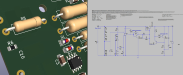
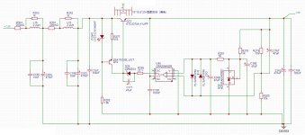
I redraw schematic for GLED431 without 20 R trimmer resistor (6,76V from 4xLED), and for 22,5 Vout, to use two types resistors only, e.g. 330R and 4.7k , max dissipation i see is ca 50mW so it`s not an issue.
On KiCad visualisation an R6 0805 is compared to R8 Vishay RN65D and indeed allows much smaller pcb even with multiple resistors in series. SMD on it`s own allows for more efficient use of PCB space as it does not collide with elements on the other side.
I`m torn between single non inductive non magnetic carbon films, Vishay RN65D or to try Vishay Melf or Susumu RG.
Still, more important question, what do the C3/C7 capacitors by feedback voltage divider on original schematic ?
SMD allows compactness but power dissipation of 0805 is prohibitively low. Good quality resistors e.g. Vishay PLTU are darn expensive, whereas Susumu RG bought in 100`s are affordable and have a good reputation. Vishay Beyschlag Melf expensive as well.
I redraw schematic for GLED431 without 20 R trimmer resistor (6,76V from 4xLED), and for 22,5 Vout, to use two types resistors only, e.g. 330R and 4.7k , max dissipation i see is ca 50mW so it`s not an issue.
On KiCad visualisation an R6 0805 is compared to R8 Vishay RN65D and indeed allows much smaller pcb even with multiple resistors in series. SMD on it`s own allows for more efficient use of PCB space as it does not collide with elements on the other side.
I`m torn between single non inductive non magnetic carbon films, Vishay RN65D or to try Vishay Melf or Susumu RG.
Still, more important question, what do the C3/C7 capacitors by feedback voltage divider on original schematic ?
Attachments
Last edited:
GLED431 needs more than 5mA, according to your calculation it turns out that the current through GLED431 will be only 1.6mA which is enough only for LEDs
My GLED431s work at much higher currents up to 28mA but that's a bit of a different beast.
My GLED431s work at much higher currents up to 28mA but that's a bit of a different beast.
Attachments
Last edited:
yes you are right, i did the GLED431 simulation on other file, with BSS139 biased to 7,8mA and ZTX, and here just used old schematic from LM329 with actualised reference value without trimmer resistor. It is not a full drawn version.
What are C3/C7 100uF on feedback voltage divider for? What would be the best resistors in feedback loop ?
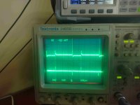
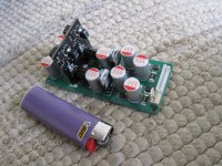
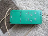
upper trace is taken from pass transistor leg, lower trace from first feedback resistor leg. Diffrence is only 15 cm of wire between, but it is clear to see that lower is much better. We hear much more than we can see on the scope.
What are C3/C7 100uF on feedback voltage divider for? What would be the best resistors in feedback loop ?
upper trace is taken from pass transistor leg, lower trace from first feedback resistor leg. Diffrence is only 15 cm of wire between, but it is clear to see that lower is much better. We hear much more than we can see on the scope.
Attachments
Last edited:
I think your efforts are misdirected. Carbon film is aboutr the worst you can get re noise and instability, the others are a waste of money in this unit.I`m torn between single non inductive non magnetic carbon films, Vishay RN65D or to try Vishay Melf or Susumu RG.
$ 0,10 metal film is OK and low cost.
R6/R7 divides the output for comparison with the ref. But that means it also decreases the loop gain because the 'error voltage' to the opamp is also divided.
C3/C7 short R6/R13 for AC so the AC feedback is not divided down, and thus does not decrease the loop gain. Result is a bit more AC loop gain and thus a bit better performance.
To be more precise: the Rout, for instance, is decreased by the feedback divider ratio compared to the situation without C3/C7.
Jan
Last edited:
If i understand properly, this capacitors increase loop gain at higher frequencies and make thus the superreg better (as long as it is stable),
so they should stay there if i care for sound quality ? Kind of increases the gain, i.e. supresses the error better at high frequencies.
I have repeatable instability on both positive and negative rail with faster op amps with 100uF in my board across R6/R13 means problems with phase margin. It can be the fault of the prototype board and countless dupont jumpers and there is a chance 100uF could work on a proper tight pcb, and or with diffrent values? I just tried some 4.7uF and 10uF across and they all cause instability, that i can cure only with 100p across pin 2 and 6 on the op-amp which defeats the purpose as it is decreaseing loop gain at high freq again..
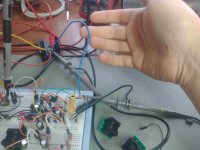
Is there a way around it without the need to buy Bode 100 ? My Analog Discovery 2 with hand drawn bifilar Vacuumschmelze toroid as injection trafo, are very non linear and are hard to draw conclusions from
so they should stay there if i care for sound quality ? Kind of increases the gain, i.e. supresses the error better at high frequencies.
I have repeatable instability on both positive and negative rail with faster op amps with 100uF in my board across R6/R13 means problems with phase margin. It can be the fault of the prototype board and countless dupont jumpers and there is a chance 100uF could work on a proper tight pcb, and or with diffrent values? I just tried some 4.7uF and 10uF across and they all cause instability, that i can cure only with 100p across pin 2 and 6 on the op-amp which defeats the purpose as it is decreaseing loop gain at high freq again..
Is there a way around it without the need to buy Bode 100 ? My Analog Discovery 2 with hand drawn bifilar Vacuumschmelze toroid as injection trafo, are very non linear and are hard to draw conclusions from
Last edited:
it seems that a fancy ADA4898-1 without those caps works better than NE5534 with them. Even small 2.2uF across divider throws ADA into instability.
my goal is to squeeze as much gain into HF.. I was planing on upgrading my AnalogDiscovery 2 to PicoScope 5443D in the near future. Would this new scope together with https://www.picotest.com/products_J2100A.html be injection trafo be good enough to play with Bode Plots and those fancy Type II and III compensation techniques ?
my goal is to squeeze as much gain into HF.. I was planing on upgrading my AnalogDiscovery 2 to PicoScope 5443D in the near future. Would this new scope together with https://www.picotest.com/products_J2100A.html be injection trafo be good enough to play with Bode Plots and those fancy Type II and III compensation techniques ?
If you want better performance in the HF area, then a shunt regulator would be a better choice.
https://refsnregs.waltjung.org/UnivReg_122714.pdf
https://refsnregs.waltjung.org/UnivReg_122714.pdf
not doable for 5 Ampere version , unless i want to switch to electric heating in winter. It must be series with minimal dropout.
I rewind my homebrew injection trafo and try to calibrate AD2 correctly, i must see these phase margins if i want to lick a knife after 4 beers with speed up caps.
I rewind my homebrew injection trafo and try to calibrate AD2 correctly, i must see these phase margins if i want to lick a knife after 4 beers with speed up caps.
I bought a pair of these boards a couple years ago and finally deciding to dig in and use them. I would like to set them up for 15V or 18V output to use with a headphone amp (15V) or a Pearl 3 Phono (18V).
I plan to buy the exact parts from the BOM and use 6.9V Zeneer, AD817, and a 1.07k resistor for R6 to get approximately 15V.
From what I understand, I need a PSU before the Super Reg. What is the simplest form of PSU I can use? I understand I need my toroidal, bridge rectifiers, some filtering, and what else?
Also, what does my voltage need to be BEFORE the Super Reg? I understand my rectified DC voltage needs to be higher than my desired voltage, correct?
I am hoping to get some feedback of what others have used and get more ideas for my build.
Stock voltage for the Pearl 3 is also +/- 15V. With 18V you will be at or over the limit of some opamps used in the Pearl3. I built super regs for my Pearl3. 1k07 is correct for 15V. I used OPA1611 opamps in the SR (less noise than the AD817). They are smd parts though.
@Wellerman
I do have some 1611 I soldered up. Too bad I already ordered the AD817….
Would love to see how you implemented it to use on the Pearl. I assume the regulators on the Pearl are removed.
Any pictures of the build?
I do have some 1611 I soldered up. Too bad I already ordered the AD817….
Would love to see how you implemented it to use on the Pearl. I assume the regulators on the Pearl are removed.
Any pictures of the build?
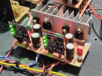
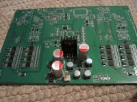
Yet another +5V J.D successor. Implemented in my next project, it work very nice, rersult was expected as Tina simulation show an nice regulator. Implemented an inline dc-dc filter at the input, and removed 330nH output inductor, had some oscilation with them but in simulation those inductor helped to linearise some characteristic but in real circuit it oscilated and gaved 0.5V more than what simulation showed, probably my bad inductor choice, so I removed them and regulator is stable and work nice : )
Attachments
Last edited:
One +5V with the best result I built stil this one https://www.diyaudio.com/community/threads/super-regulator.247281/post-7537194
This one curently untested, +-15V for preamp supply, powered from SMPS400A180 aux, contain inline dc-dc filter, lm317/337 predregulators and micro J.D. regulators, microregulators gerber and bom I have posted in one of my earliers posts, good results with those micro J.D. who want to builld. : )
Attachments
Last edited:
- Home
- The diyAudio Store
- Super Regulator