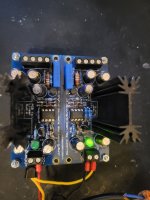
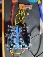
Hello, I have a problem with my super regulator.
When I apply a voltage of 22V, the minus LED on the output side does not light up and the plus LED does not.
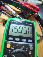
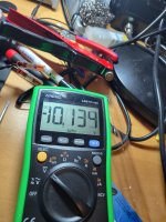
With the cables connected, the plus LED also lights up and I can set 15V on the plus side and max. 10V on the minus side.
I have checked the components but cannot find a fault.
When I apply a voltage of 22V, the minus LED on the output side does not light up and the plus LED does not.
With the cables connected, the plus LED also lights up and I can set 15V on the plus side and max. 10V on the minus side.
I have checked the components but cannot find a fault.
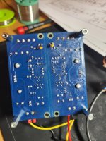
Attachments
@grunf schematic is this. Input 12V and output 5 V. It works with OPA1611 and output is 5V. R6 is adjustable resistor. When I insert ADA4897 then the voltage with a same parts is 3.6V. Do I now need to change some resistor values to get with this op amp 5V? Changing R6 now does not change output at all. It changed with using OPA1611. For next step I was planning to replace R5 with CCS using CPH3910 and resistor value I do not know. One of your schematics you used 68.1 ohm and on JLH monster psu 330 ohm. The J-Fet is different. If someone could tell me the right resistor value for this CCS then I would be happy. For the output 1.5 amps.
Another issue I have is that my input voltage is too high 12 DC. I do not have another transformer. What kind of CCS I can use to make voltage drop and improve this regulator and it is not getting too hot? I am using with soundcard 1.5A and I can not use multiple PSU-s. Only one voltage input on Volt 476 soundcard.

Another issue I have is that my input voltage is too high 12 DC. I do not have another transformer. What kind of CCS I can use to make voltage drop and improve this regulator and it is not getting too hot? I am using with soundcard 1.5A and I can not use multiple PSU-s. Only one voltage input on Volt 476 soundcard.
One way to drop +12VDC down to +7.5VDC is to connect a 4.3 volt, 5 watt Zener diode (like 1N5336B) in series between +12VDC and your regulator. Of course this only works if your output current is less than 500 milliamps. If your output current is more than 500 milliamps you can use a 10 watt power resistor and Ohm's Law. Just solve this equation for resistance: (Current * Resistance) = (12 - 7.5).
I tried before 3 and 4 ohm resistors but they went also very hot using 20W rated resistors. My regulator uses 1.5-2 A. Maybe is there a better solution or I just have to get new transformer.One way to drop +12VDC down to +7.5VDC is to connect a 4.3 volt, 5 watt Zener diode (like 1N5336B) in series between +12VDC and your regulator. Of course this only works if your output current is less than 500 milliamps. If your output current is more than 500 milliamps you can use a 10 watt power resistor and Ohm's Law. Just solve this equation for resistance: (Current * Resistance) = (12 - 7.5).
I tried also one pre regulator that I had but it gets also quite hot and I dont like that. Also I noticed, that it affected a little bit sound quality.@viltsone
Use an adjustable pre-regulator to set the input voltage you want the SR to see?
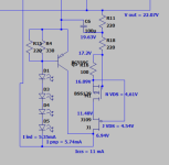
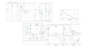
what does the Q2 transistor in your GLED Voltage reference ? I recall only the Q1 from original article from Walt. What do the R4 R5 and C1 ? What are they for ?I just modeled GLED431 with CCS for negative part of Jung/Didden Superregulator. I would be very happy if someone can comment and point to any mistakes. Current through R6 (390R) 5mA.
In the post #3331 there is a link to article marked as confidential draft. I do not know if I can repost it. But you can look at it on page 168. R4, R5 and C1 is modified cascode current source with bias multipler as in audioXpress 4/09 page 40. Also somewhere is a link to it.
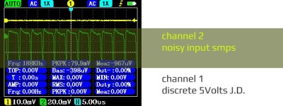
In relation to post 3382 , bad news it not going to work corectly, flyback topology is simply not very user friendly for audio things, getting huge noise > 10mV at j.d. regulators. And also reguire huge load > 50% to work corectly, even it not, I think I will not waste my time anymore with flyback, instead I will go for push pull topology next time as one which work very good with j.d. , getting noise with it about <=10uV
Last edited:
I found a picture from audioXpress:In the post #3331 there is a link to article marked as confidential draft. I do not know if I can repost it. But you can look at it on page 168. R4, R5 and C1 is modified cascode current source with bias multipler as in audioXpress 4/09 page 40. Also somewhere is a link to it.
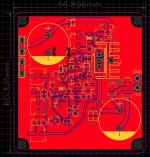
in order to decide - whether all this fuss with discrete GLED 431 controlled by a fancy constant current source is worth the hassle against simple resistor with LM329, I decided to design a new pcb with GLED and CCS as separate small pcbs with legout as 15.24mm pitch, and make it parallel to lm329. Only then, on the same amplifier and the same pcb, after listening,i can decide if it's worth extra part count and solder points, plus high prices of Avago HLMP 6000 and ztx951.
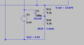
In case of my 11 mA ccs (left) i still had voltage headroom for a bootstrap with 2x220R+100uF. In case of LM329 i must bias it to >1mA but not as much as GLED, so i would swap 2x220 to 2x4700. If i remove the C6 i'm back to basics. I doubt i can measure any difference, but i already know i hear much more that i can measure.
In case of my 11 mA ccs (left) i still had voltage headroom for a bootstrap with 2x220R+100uF. In case of LM329 i must bias it to >1mA but not as much as GLED, so i would swap 2x220 to 2x4700. If i remove the C6 i'm back to basics. I doubt i can measure any difference, but i already know i hear much more that i can measure.
Attachments
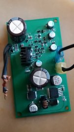
Discrete J.D 5Volts with integrated XL4015 buck as a predregulator. Noisy smps at the input and xl4015 integrated into pcb + discrete J.D. cleaned moise up to almost 100% : )
Version 2 is with beter inline dc filter, pcb is version 1
Version 2 is with beter inline dc filter, pcb is version 1
Attachments
Last edited:
to be absolutely sure, that it was not worth the hassle.Why so expensive leds?
I need some help with negative regulator to get to work. Led is not working and output voltage is as about the input voltage. Op amp OPA1611 gets very hot. Maybe got damaged? I removed Q4 and still it gets hot in seconds. Voltage difference between resistor R10 was about 0,5 V. Op amp pin 2 and 3 voltage difference about 1 V. I measured Q3 and Q4 with DMM and its kinda a same resistance as new ones. Changing op amp does not work. Tried for a very short time to not damage or overheat some parts.
Any ideas what to test or change?

Any ideas what to test or change?
- Home
- The diyAudio Store
- Super Regulator