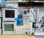
And so. About the noise of this regulator.
New measurement. Regulator supply from unregulated psu. Opamp supply also from unregulared input as a schematic.
For easier understanding, the readings of the analyzer are in µV/√Hz.
Tombo, really the analyzer is wrong at levels below -120 db or I have calibration problems at these levels.
When I have time, I will give it a fresh calibration.
At high levels not problems. Furthermore its specifications are down to 1 microvolt (-120dB)
So at such low levels it is good to have LNA before it.
I did measurements. All measurements are at gain 100 (40dB).
I did the calculations. I don't know if I'm wrong somewhere. I don't have a deep knowledge of analog circuitry and especially noise.
You have a lot of experience and knowledge and I hope you can tell me now if everything is correct.
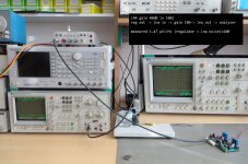
LNA noise at gain 100 (50R terminated) = 0.12µV/√Hz
----------------------------------
at gain 1 = 0.12/100 = 0.0012 = 1.2nV/√Hz = 1.2*√25000 = 1.2*158.11 = ~190nV
measured noise (1K5 resistor + LNA) at gain 100 = 0.49µV/√Hz
--------------------------------------------------------------------
at gain 1 = 0.49/100 = 0.0049 = 4.9nV/√Hz = 4.9*√25000 = 4.9*158.11= ~775nV
measured 1K5 resistor noise = √(775^2-190^2) = ~751nV
(theoretical thermal noise = 789nV)
measured noise (regulator + LNA) at gain 100 = 1.47µV/√Hz
--------------------------------------------------------------------
at gain 1 = 1.47/100 = 0.0147 = 14.7nV/√Hz = 14.7*√25000 = 14.7*158.11= ~2324nV = ~ 2.32µV
LNA noise = 190nV = 0.19µV
measured regulator noise = √(2.32^2-0.19^2) = ~ 2.31µV
regulator noise (video)
1K5 resistor noise (video)
LNA noise (video)
New measurement. Regulator supply from unregulated psu. Opamp supply also from unregulared input as a schematic.
For easier understanding, the readings of the analyzer are in µV/√Hz.
Tombo, really the analyzer is wrong at levels below -120 db or I have calibration problems at these levels.
When I have time, I will give it a fresh calibration.
At high levels not problems. Furthermore its specifications are down to 1 microvolt (-120dB)
So at such low levels it is good to have LNA before it.
I did measurements. All measurements are at gain 100 (40dB).
I did the calculations. I don't know if I'm wrong somewhere. I don't have a deep knowledge of analog circuitry and especially noise.
You have a lot of experience and knowledge and I hope you can tell me now if everything is correct.
LNA noise at gain 100 (50R terminated) = 0.12µV/√Hz
----------------------------------
at gain 1 = 0.12/100 = 0.0012 = 1.2nV/√Hz = 1.2*√25000 = 1.2*158.11 = ~190nV
measured noise (1K5 resistor + LNA) at gain 100 = 0.49µV/√Hz
--------------------------------------------------------------------
at gain 1 = 0.49/100 = 0.0049 = 4.9nV/√Hz = 4.9*√25000 = 4.9*158.11= ~775nV
measured 1K5 resistor noise = √(775^2-190^2) = ~751nV
(theoretical thermal noise = 789nV)
measured noise (regulator + LNA) at gain 100 = 1.47µV/√Hz
--------------------------------------------------------------------
at gain 1 = 1.47/100 = 0.0147 = 14.7nV/√Hz = 14.7*√25000 = 14.7*158.11= ~2324nV = ~ 2.32µV
LNA noise = 190nV = 0.19µV
measured regulator noise = √(2.32^2-0.19^2) = ~ 2.31µV
regulator noise (video)
1K5 resistor noise (video)
LNA noise (video)
Attachments
Last edited:
")
Hi everyone!
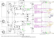
I read the whole thread but haven't found anything about Kevin Gilmore golden reference low voltage power supply (GRLV for short).
It is interesting because it inverts diode switching noise (transistor circuit on the input of the regulator).
Original power supply measures bellow 1uV of noise.
I am using the positive half for my DAC and as always I am looking for a way to improve it.
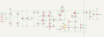
I attached the original bipolar supply and my modded positive supply schemes.
-I changed the voltage reference for two diodes. Because of low regulator output the voltage reference ccs wasn't getting enough voltage to work with. Leds improved the regulation and sound drastically. Diodes are low noise HLMP-6000.
All of these changes made very big difference.
Btw I am using custom made smd DDDAC1794A by Doede Douma.
Are leds quiet enough to replace voltage reference in my case?
Is there a need for darlington pass transistor? I read that because of it regulator has higher input and lower output impedance, but it is slower.
I would very much appreciate your advices and critics.
I read the whole thread but haven't found anything about Kevin Gilmore golden reference low voltage power supply (GRLV for short).
It is interesting because it inverts diode switching noise (transistor circuit on the input of the regulator).
Original power supply measures bellow 1uV of noise.
I am using the positive half for my DAC and as always I am looking for a way to improve it.
I attached the original bipolar supply and my modded positive supply schemes.
-I changed the voltage reference for two diodes. Because of low regulator output the voltage reference ccs wasn't getting enough voltage to work with. Leds improved the regulation and sound drastically. Diodes are low noise HLMP-6000.
- Opamp protection diodes were omitted
- CCS mosfet was changed
All of these changes made very big difference.
Btw I am using custom made smd DDDAC1794A by Doede Douma.
Are leds quiet enough to replace voltage reference in my case?
Is there a need for darlington pass transistor? I read that because of it regulator has higher input and lower output impedance, but it is slower.
I would very much appreciate your advices and critics.
Attachments
Thank you for your answer!
This should be an improved super regulator. The topology is the same. Correct me if I am wrong.
I posted here because i wanted to know if this "improvements" are worthwile and maybe some parts of original super regulator are better than those in my diy super regulator.
All in all I would like to change parts of this regulator and listen for a differences
I wouldn't really say that it is an improved super regulator, it can still be improved a lot and some shortcomings of that design need to be corrected.Thank you for your answer!
This should be an improved super regulator. The topology is the same. Correct me if I am wrong.
I posted here because i wanted to know if this "improvements" are worthwile and maybe some parts of original super regulator are better than those in my diy super regulator.
All in all I would like to change parts of this regulator and listen for a differences
@juliobozek Thank you for asking about Kevin Gilmore golden reference low voltage power supply. I had same question and I recently found out about this schematic. I really like to see new improved super regulator. I do not have any background to engineer one for myself. I just feel and hear the difference and I love music that flows and enlightens me. I have seen many improvement ideas put not a full schematic that takes them all a count.
@jan.didden Any plan to update this super regulator and PCB-s in Diyaudio store? I really love to see that. It could be 2 versions one for lower amps and a upgrade to up to like 2 amps version using the same PCB.
@grunf What would be good available replacement part for 2SK246, 2SK35577 and can I use it with your JLH69 version regulator this also? Also I like to add your JLH69 version this input CCS with right parts to get 5V and 2A out.
https://www.diyaudio.com/community/threads/walt-jung-shunt-design.383690/post-7016961

grunf another version of JLH69 regulator

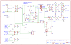
I have built this following grunf JLH69 version ( on the 3rd picture) using Q1,2 - DB140 and 2SC2500. 5V out and using it to power soundcard consumption with 1.5 amps. Can I just add J1 and Q3, Q4 from upper schematic to this my built one to improve this regulator further more? I also like to add this CCS that was used in the first picture using right parts to this schematic what I have built. I really need help and guidance for that.

Thank you!
@jan.didden Any plan to update this super regulator and PCB-s in Diyaudio store? I really love to see that. It could be 2 versions one for lower amps and a upgrade to up to like 2 amps version using the same PCB.
@grunf What would be good available replacement part for 2SK246, 2SK35577 and can I use it with your JLH69 version regulator this also? Also I like to add your JLH69 version this input CCS with right parts to get 5V and 2A out.
https://www.diyaudio.com/community/threads/walt-jung-shunt-design.383690/post-7016961
grunf another version of JLH69 regulator
I have built this following grunf JLH69 version ( on the 3rd picture) using Q1,2 - DB140 and 2SC2500. 5V out and using it to power soundcard consumption with 1.5 amps. Can I just add J1 and Q3, Q4 from upper schematic to this my built one to improve this regulator further more? I also like to add this CCS that was used in the first picture using right parts to this schematic what I have built. I really need help and guidance for that.
Thank you!
Hi everyone!
I read the whole thread but haven't found anything about Kevin Gilmore golden reference low voltage power supply (GRLV for short).
It is interesting because it inverts diode switching noise (transistor circuit on the input of the regulator).
Original power supply measures bellow 1uV of noise.
I am using the positive half for my DAC and as always I am looking for a way to improve it.
I attached the original bipolar supply and my modded positive supply schemes.
-I changed the voltage reference for two diodes. Because of low regulator output the voltage reference ccs wasn't getting enough voltage to work with. Leds improved the regulation and sound drastically. Diodes are low noise HLMP-6000.
- Opamp protection diodes were omitted
- CCS mosfet was changed
All of these changes made very big difference.
Btw I am using custom made smd DDDAC1794A by Doede Douma.
Are leds quiet enough to replace voltage reference in my case?
Is there a need for darlington pass transistor? I read that because of it regulator has higher input and lower output impedance, but it is slower.
I would very much appreciate your advices and critics.
Hi, do you mean "it inverts diode switching noise (transistor circuit on the input of the regulator)" is Q3, Q6, Q7 from second schematic?
Pondering this off and on since seeing Jan's giving advice on using the negative board for a positive application. In using a negative board for positive application (or vice versa) is there no difference from using a positive board for the same positive application? It would seem on the surface there'd be little point in bothering with two designs if they're effectively the same.
Thanks
Thanks
All the caps must be soldered with vicewersa polarity. All diodes too. pnp/npn is now npn/pnp. The only thing which break layout is opamp! Opamp VCC and gnd is now diferent and it is the only thing which have problem to use an an positive regulator pcb for negative and vicewersa! : )
Last edited:
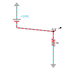
My question is not that complicated.
I'm referring to something like the attached image. The positive output of the supply is at common potential so it's own return becomes a negative voltage source.
Conversely, If the negative output of a negative supply is set at circuit common, its return becomes a + voltage for the circuit it's connected to.
Bias supplies for tube circuits have been built either way. In the case of the Super-Reg , where its designer has supported use (in a pinch?) in this way, I'm wondering what differences (or drawbacks) there may be between each in the same application. That's all.
Attachments
Edit: The context for the above question is that I have a positive Super Reg biasing a breadboarded transmitting triode grid positive for A2. So far, successfully.
If the circuit turns out to be worth building a second channel for stereo, rather than use another positive board (resulting in two unused -V supply pcbs) I wonder what potential trouble might be there if the -V board is used for +V grid bias.
Thinking about this, then if in use there is no practical difference. why bother having two designs?
Or, if there is a situation where the alternative hookup is not optimal, then what are the limiting conditions?
Thanks again!
Hearinspace -
See Jan’s post # 3266
Or - on your negative board
Reverse all electrolytic capacitors / D6 D7
You will reverse D10 but you are reversing pins 2 & 3 only - so pin 1 of D10 you can cut off
Cut the pc traces from U2 Pin 7 to ground, and U2 Pin 4 to emitter of Q3
Install Jumpers from U2 Pin 4 to ground and U2 pin 7 to emitter of Q3
And of course use D44H11 for Q3 and BC556 for Q4
HI and thanks . Yes, I understand all this. I guess the question is more about the electrons than the nominal use in this or that application.
Its why I worded the question the way I did. If either board can be used "as a battery" in the same application, there must be at least some difference there somewhere, though you might have to be an electron to see it. The two "batteries" are different after all, and might not necessarily behave equally under every conceivable condition. The differences may have absolutely no bearing on concerns for the practical application, though might be a topic for a physics thesis. While I think it's natural to wonder how much it will like clamping a transmitter grid being swung by a very dynamic driver my question here is more out of pure interest. Thanks.
Its why I worded the question the way I did. If either board can be used "as a battery" in the same application, there must be at least some difference there somewhere, though you might have to be an electron to see it. The two "batteries" are different after all, and might not necessarily behave equally under every conceivable condition. The differences may have absolutely no bearing on concerns for the practical application, though might be a topic for a physics thesis. While I think it's natural to wonder how much it will like clamping a transmitter grid being swung by a very dynamic driver my question here is more out of pure interest. Thanks.
- Home
- The diyAudio Store
- Super Regulator