Thanks Jan, I've dropped R1 to 180R and it's holding 12.17V now ") . The voltages check out better now too.
. The voltages check out better now too.

D2 wasn't orientated specifically in the photos, but good spot. I changed D2 at the same time as replacing R1, just to be sure.
Apologies for the current confusion, schoolboy error. I should, and do, know better, I'm somewhat surprised I made that mistake once let alone twice. Anyway, I really appreciate your support on this, I don't need to tell you how good it sounds.
. The voltages check out better now too.D2 wasn't orientated specifically in the photos, but good spot. I changed D2 at the same time as replacing R1, just to be sure.
Apologies for the current confusion, schoolboy error. I should, and do, know better, I'm somewhat surprised I made that mistake once let alone twice. Anyway, I really appreciate your support on this, I don't need to tell you how good it sounds
.Hello;
As an amateur, my questions may be simple for you, but your answers will be useful for me.
*Can I use the reference pcb in Diyaudiostore with AD797 without any problems? I have 6 pieces in stock
*Which voltage reference integration should I use for 3.3v and 5 volts. Is LM4040 2.5v a good choice?
*Can I use BC850C and860C Q2 and Q4?
*Can I get 1A continuously with the reference schematic?
*Can 5 volts and 3.3V be used in delta sigma dacs or R2R nos dacs? Is the Load Transient Response sufficient for digital audio applications or is it better in analog stage?
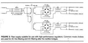
**Would there be any advantage of a CLC style filtering on the input of the regulator?
Thank you very much
As an amateur, my questions may be simple for you, but your answers will be useful for me.
*Can I use the reference pcb in Diyaudiostore with AD797 without any problems? I have 6 pieces in stock
*Which voltage reference integration should I use for 3.3v and 5 volts. Is LM4040 2.5v a good choice?
*Can I use BC850C and860C Q2 and Q4?
*Can I get 1A continuously with the reference schematic?
*Can 5 volts and 3.3V be used in delta sigma dacs or R2R nos dacs? Is the Load Transient Response sufficient for digital audio applications or is it better in analog stage?
**Would there be any advantage of a CLC style filtering on the input of the regulator?
Thank you very much
Attachments
Last edited:
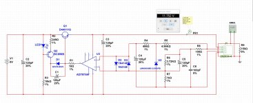
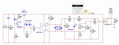
I tried to simulate the voltages I wanted.
I will try to test the reference schematic in real time with AD797 and AD817.
I would like to ask;
*I understand from what I read that the opamps I need to use for 3.3V;
AD8031 - ADA4099-1 - MCP6021,...
AD797 can be used for 5V and other voltages....
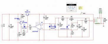
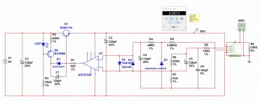
*As far as I read from the article, it says that for 5V, R5 (my schematic) should be 2.49K and R3 (my schematic) should be 4.99k. Should the schematic in diyaudiostore also be changed?
I will try to test the reference schematic in real time with AD797 and AD817.
I would like to ask;
*I understand from what I read that the opamps I need to use for 3.3V;
AD8031 - ADA4099-1 - MCP6021,...
AD797 can be used for 5V and other voltages....
*As far as I read from the article, it says that for 5V, R5 (my schematic) should be 2.49K and R3 (my schematic) should be 4.99k. Should the schematic in diyaudiostore also be changed?
Attachments
Hmmm oscillate... What should I do to avoid oscillation?
Can I use AD825 or AD817 for 5V?
As far as I read from the article, it says that for 5V, R5 (my schematic) should be 2.49K and R3 (my schematic) should be 4.99k. Should the schematic in diyaudiostore also be changed?
Can I use AD825 or AD817 for 5V?
As far as I read from the article, it says that for 5V, R5 (my schematic) should be 2.49K and R3 (my schematic) should be 4.99k. Should the schematic in diyaudiostore also be changed?
Last edited:
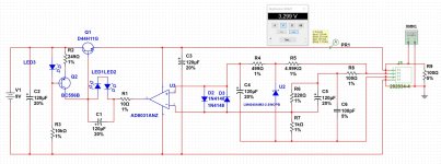
There is an error in the schematics attached at this post at the opamp output.I tried to simulate the voltages I wanted.
I will try to test the reference schematic in real time with AD797 and AD817.
I would like to ask;
*I understand from what I read that the opamps I need to use for 3.3V;
AD8031 - ADA4099-1 - MCP6021,...
AD797 can be used for 5V and other voltages....
*As far as I read from the article, it says that for 5V, R5 (my schematic) should be 2.49K and R3 (my schematic) should be 4.99k. Should the schematic in diyaudiostore also be changed?
Jan
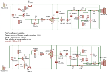
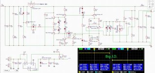
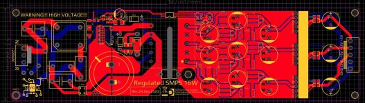
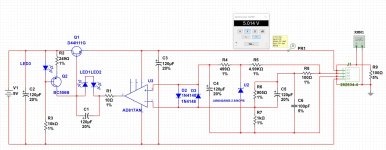
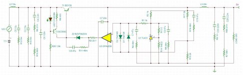
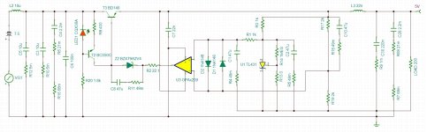
Today I have finished discrete J.D. and results is very good, this is final schematic and measurement for discrete version 5V, picture 1 and 2. Picture 3 and 4 is micro version, 3 micro j.d. regulators (+15V, -15V, +5V) connected to the TNY smps diy mainboard (picture 5), with strong filtering, results soon!
Attachments
![DSC_2198[1].JPG](/community/data/attachments/1130/1130777-a2efdd1dc6ffa84dda5258745c37754f.jpg)
![DSC_2200[1].JPG](/community/data/attachments/1130/1130780-7eb4bbc084092bda6efeb0626c279816.jpg)
![DSC_2201[1].JPG](/community/data/attachments/1130/1130781-4469399557f8e7e828ade6a9e89c6d43.jpg)
Last edited:
I started reading the super regulator discussions from the first page, I am now on page 40.
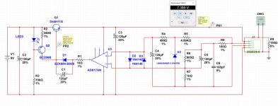
My simulation could not simulate for 5volt and 3.3Volt with 6,8V zener. When I learnt that a few people in the forum made the 5volt application with two series LEDs, I simulated in this way. "I would like to point out that the 6V8 zener 12V 15V 18V worked in the simulation."
I will continue my way with AD817. Because the voltages I want are 5V 12V 12V 15V 18V. I gave the components orders, I will order the pcb after real-time tests.
Finally, as you mentioned in your article, should we use a 7.5v or 8.2v zener for the output voltage after 15v, for example 18v?
Thanks for your understanding and patience @jan.didden
Attachments
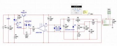
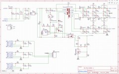
@sercan85 take a look at schematic for 5V version, I have sucess in micro version using OPA209 , it work very good! But discrete version is better a bit. Resistor from schematic like R1, R10, R6, R11... is not a resistors but ESR values of the capacitors, I put them just for simulation. R7, R16... is real resistors. Forget 3.3V version, it not going to work well, instead put an linear regulator to the existing 5V j.d. and it will work well, e.g. LT3042
Attachments
Last edited:
- Home
- The diyAudio Store
- Super Regulator