Hello, I am planning on building an Aleph J board with obviously a +/-24v PSU, and all of my other equipment is XLR (balanced). To convert the XLR signal to RCA, I am using a converter which requires 12v 1a. I noticed this board has a max reference voltage of 10v, does this mean thats the maximum input voltage? Thus I can’t really use this board for my purpose?
Thanks
Thanks
Bergenton - Yes - you can use a SuperReg for your 12 V convertor.
Use an LM329 6.9 VREF for D5
R7 = 1.18 K
R6 = 768 ohm
D2 = 1N5233
Why not treat yourself and build a +/- 24V SuperReg for the Aleph J ?
I find SuperRegs are an excellent compliment to discreet line stages.
Use an LM329 6.9 VREF for D5
R7 = 1.18 K
R6 = 768 ohm
D2 = 1N5233
Why not treat yourself and build a +/- 24V SuperReg for the Aleph J ?
I find SuperRegs are an excellent compliment to discreet line stages.
Dvd,
Thanks for the quick replies. I am planning on building a regular PSU for the Aleph J using the Universal board in the store. I want to power the additional board (12v, 1A) within the same chassis, but also use the same power supply that I'm using for the Aleph J.
So I was under the impression that the SuperReg is a sort of an adjustable step down convertor that I can run in parallel with the main PSU, since I'd need to step 18v down to 12v.
Thanks!
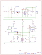
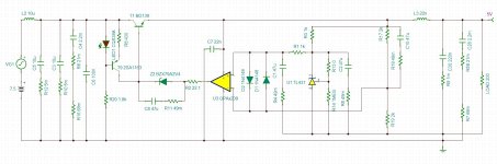
@grunf Could you please guide me what changes I have to make to use your schematic in 5V out version? I like to get out 1,5-2 A.The new version is no longer so simple, now it has 13 transistors (10 SMD) and does not use any zener diodes or references. All parts of the schematic are not mine, so the publication will have to wait.
To begin with, I am attaching the first test version that I used in JLH69, instead of KTD2061/KTB1369, TTC004/TTA004 or the popular BD139/140 can be used.
Any news about new improved regulator?
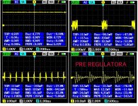
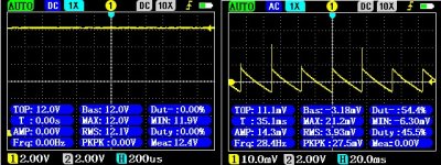
To bad news for my iso push pull super reg version, push pull iso pre regualtor work very well, but J.D. discrete supereg seems have problem with layout? If I put an linear fixed 5V regulator in place of J.D. there is no isue so problem come definitely from discrete J.D . Pre regulator deliver 7.5V but I have put it on 12V with no diference. Previous implementation was almost promissing but something is happened with this smaler version, can you please tell me do you see something which I don't, it have some strange oscilations and I am unable to figure them out, looks like a layout isue? Isue is reflected even to pre regulator, which can be seen in the lower right window in the first picture, what might be isue here? I thought I'd share this with you after full testing it as it works very well on the previous biger non-isolated implementation, too bad : (
Attachments
Last edited:
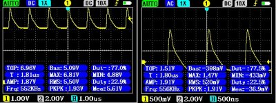
I discovered something interesting about this regulator. When I connect it to an external 12V voltage that has a sawtooth signal, it seems to me that this j.d. the mini regulator amplifies that signal instead of correcting it, why? What might be wrong, do you have any idea?
Picture 1 is j.d. regulator characteristic and picture 2 is external 12V pre regulator
EDIT:
OMG! I forgot two resistors between Q2 and Q3 : ( might that be the source of problem?
Picture 1 is j.d. regulator characteristic and picture 2 is external 12V pre regulator
EDIT:
OMG! I forgot two resistors between Q2 and Q3 : ( might that be the source of problem?
Attachments
Last edited:
Hello all, I wanted to ask what are probably a couple of daft questions if you don't mind. I'm putting together an active crossover for a pair of old Tannoy MG12s using the OPA1656 and wanted to idiot check myself really as I'm learning as I go....
The super regulator here is likely a good candidate for the power supply right? Then a15v / 18v power supply would work well for the opamps? It seems an easy midpoint on the min / max from the data sheet. There's 3 opamps per board, each board managing 1 of the 2 channels. Nothing sounds wildly wrong here does it? Thanks for any help and advice!
The super regulator here is likely a good candidate for the power supply right? Then a15v / 18v power supply would work well for the opamps? It seems an easy midpoint on the min / max from the data sheet. There's 3 opamps per board, each board managing 1 of the 2 channels. Nothing sounds wildly wrong here does it? Thanks for any help and advice!
Somewhere on this thread someone build a phono and powered all op amps with a super reg. A ambitious project it was mentioned. Now i want to do the same with a dac project. But i need some advice regarding: "And, don’t put a high-quality film cap at the output of the regulator! The reg likes to see some lossy capacitance at the output for stability".
Lets asume i have a dac chip (for example ad1862) with some fast op amps as i/v.:
-Dac digital power
-dac analog power
-op amps power
Of course i'm gonne place the output and sense right next to all the ic legs where the power goes in (no reservoir caps also). But the datasheat of the ic's mentions 100nf decoupling for low impedance. Here's my conflict. Omit these (the SR can supply this low impedance?), or if i need to place these caps, can the SR handle these 100nf caps at the output?
I’m using JD superreg’s for each PSU connection in my DAC (9x LM317 pre-
Regulators with each followed by a JD).
I’m using 100nf COG as decoupling, I don’t have issues.
https://www.diyaudio.com/community/threads/super-regulator.247281/page-162#post-7428304
Regulators with each followed by a JD).
I’m using 100nf COG as decoupling, I don’t have issues.
https://www.diyaudio.com/community/threads/super-regulator.247281/page-162#post-7428304

put the decoupling caps near the pins of the device your are supplying from the SR. The little bit of resistance and inductance from SR to opamp works to your advantage.
in my Adcom GFP565 with SR I put 10R on the sense lines.
the advice suggesting NOT using decoupling caps on the error amplifier was probably in reference to issues with the AD797 used as error amplifier mentioned in the 1995 TAA articles. The AD797 can allow one to achieve output impedance in the low micro-Ohms at the expense of oscillation!
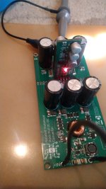
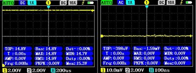
I didn't had luck this time with discrete version, I'll try to make a different layout because I know that regulator will work because the bigger version works well, very good transient response, so this mini version must work too, I won't give up! This is the good result with SA5534 mini version (black one on the picture) I made recently
Attachments
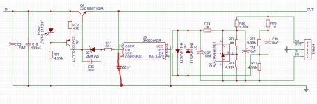
Done all 3 voltages needed for DSC single ended dac with tone control, mfb, diff, it is as a frontend for ucd180hxr. All 3 votages is stable as in previous post. 5V schematic resistor values is in atachment, the rest of components is like in previous post except resistor values, opamp and zener diode. Opamp here is opa209, for +-15V it is sa5534. Instead of posting gerber,bom,schematic I will open new thread when fully test all things together, you will get push pull iso pre regulator, 3 j.d. regulators, and frontend for ucd, all going open source soon!
Attachments
Last edited:
Maybe a little bit off topic, but i was wondering if for digital (dac digital part, xo boards, usb boards etc) these SR are suited? Jan Didden stated in this thread that with digital local decoupling is important or apply a shunt reg with a inch spacing.
So, if i use these boards only for analog, what whould be a good simple shunt circuit (Tentlabs/WJ design?), or would a lt3015/1936 be a good cannidad for digital instead of the SR.
So, if i use these boards only for analog, what whould be a good simple shunt circuit (Tentlabs/WJ design?), or would a lt3015/1936 be a good cannidad for digital instead of the SR.
The new version is no longer so simple, now it has 13 transistors (10 SMD) and does not use any zener diodes or references. All parts of the schematic are not mine, so the publication will have to wait.
To begin with, I am attaching the first test version that I used in JLH69, instead of KTD2061/KTB1369, TTC004/TTA004 or the popular BD139/140 can be used.
I modified this schemaic to 5V version. D2 I am using 2,4V zener 0,5W because from local shop they have only this close to 2,5V. For D4 I am using LM4040 2,5V. Q1 and Q2 re BD140 and 2SC5200 for Qizl. D1 is GREEN Led. Input 13 V ac 3 Amps. OPA1611. R6 value is parallel combination with resistor and trim pot.
Problem is that Qizl 2SC5200 gets very hot in 3 minutes so I can not hold more than 3 seconds my finger on the SK-129-50 heatsink. What kind of heatsink is good to use for 2 amps output and what changes to make in this schematic for better reliability and noise specs?
Any suggestions for 1 V reference to use with OPA1641? Using Leds?
- Home
- The diyAudio Store
- Super Regulator