Update for post 3202:
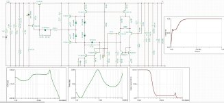
Since at the SteadyState point, after a brief StartUP interval, we will have a stable output voltage with very little drift, we have used REF for CCS of discrete opamp with resistor R9 instead of LED. The voltage drop on R9 will now be the REF input diff. and VAS.
TL431 feels great with 2.5mA. We have an output voltage of 5V, REF is 2.5V. We are left with 2.5V bias 2.5mA, which gives us 1K, which we distribute to R8+R9. We put 420R each, together it have 840R, which gives a bias of 3mA, which is also OK.
CCS
420R with a bias of 3mA gives us a voltage drop of 1.25V, half of the previous 2.5V, which we divided into two equal resistors. T3 and T13 have Ube of approx. 0.65V. We have R42 and R52 from 220R, CCS T3 and T13 give us approx. (1.25-0.65)V / 220R = 2.75mA
VAS
CCS diff = 2.75mA, divided into two branches =>1.375mA going to T5 and R46 330R) and the same amount to (T6 and R45 330R)
The voltages on the collector of T5 and T6 tend to be equal, that is (330R * 1.375mA) + UbeT6 (0.65V) = 1.10V and that voltage should be:
2.75mA*R47(10R) + UbeT11(0.65V) + UbeT7(0.65V) = 1.328V
The current mirror is a bit "too short" for us, we need R45 and R46 from:
1.328V-UbeT6(0.65V)/1.375mA = 493R
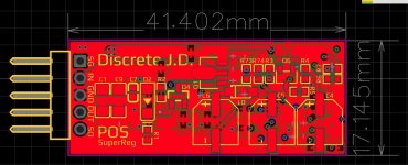
So in diference to previous schematic we just need to replace R45 and R46 with 510R and thats all! Look promising? I going to make mini discrete J.D. similar to one from post 3195 and I will share with you gerber+bom file! : )
Since at the SteadyState point, after a brief StartUP interval, we will have a stable output voltage with very little drift, we have used REF for CCS of discrete opamp with resistor R9 instead of LED. The voltage drop on R9 will now be the REF input diff. and VAS.
TL431 feels great with 2.5mA. We have an output voltage of 5V, REF is 2.5V. We are left with 2.5V bias 2.5mA, which gives us 1K, which we distribute to R8+R9. We put 420R each, together it have 840R, which gives a bias of 3mA, which is also OK.
CCS
420R with a bias of 3mA gives us a voltage drop of 1.25V, half of the previous 2.5V, which we divided into two equal resistors. T3 and T13 have Ube of approx. 0.65V. We have R42 and R52 from 220R, CCS T3 and T13 give us approx. (1.25-0.65)V / 220R = 2.75mA
VAS
CCS diff = 2.75mA, divided into two branches =>1.375mA going to T5 and R46 330R) and the same amount to (T6 and R45 330R)
The voltages on the collector of T5 and T6 tend to be equal, that is (330R * 1.375mA) + UbeT6 (0.65V) = 1.10V and that voltage should be:
2.75mA*R47(10R) + UbeT11(0.65V) + UbeT7(0.65V) = 1.328V
The current mirror is a bit "too short" for us, we need R45 and R46 from:
1.328V-UbeT6(0.65V)/1.375mA = 493R
So in diference to previous schematic we just need to replace R45 and R46 with 510R and thats all! Look promising? I going to make mini discrete J.D. similar to one from post 3195 and I will share with you gerber+bom file! : )
Last edited:
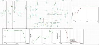
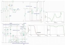
Final sim model. Added another tl431, this allow us to make negative reg. With L3 psrr is smothed and better for about -20db at around 5MHz : ) Feedback is now at pre L3 since first real model preliminary tests done in post 3200 proved that if feedback is at post L3 it cause oscilations, now after moving feedback at pre L3 there is no more oscilations, now my osciloscope take limit 10mV div and unable to measure : )
Attachments
Last edited:
Make sure you include all three effects in your simulation model(s) of each inductor: self-inductance, self-capacitance, and DC series resistance.
Also make sure you include all three effects in your simulation model(s) of each electrolytic capacitor: self-capacitance, equivalent series inductance "ESL", and equivalent series resistance "ESR".
Inductor datasheets often tell you the frequency at which the self-inductance and the self-capacitance form an LC resonant circuit. Usually it is called "Self Resonant Frequency" on the datasheet. When you know both L and f_resonant, you can easily calculate C_self.
Capacitor datasheets regrettably do not follow suit. You'll always need to measure or estimate ESL, and in many cases you'll need to measure or estimate ESR. Pages 4 thru 7 of Cornell Dubilier's supremely excellent Aluminum Electrolytic Application Guide provide a fantastic introduction to the topic. And for laboratory techniques, I strongly recommend video #100 from YouTube presenter w2aew: Capacitor self-resonance measured with an oscilloscope. Brilliant.
When you get self-resonance under control, I'm confident you will be able to improve PSRR at 5 MHz tremendously. And don't forget about adding ferrite beads as well; they are purpose-built and carefully optimized for eliminating HF noise. At very low cost! I am fond of beads made by Laird and especially part number 28C0236-0EW-10 . It may or may not be a good fit for your Super Regulator application.
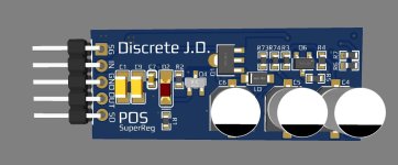
Thanks! Added that in simulation allready! I made gerber, bom, schematic. I'm not satisfied with the layout, but I'll try it anyway! : )
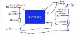
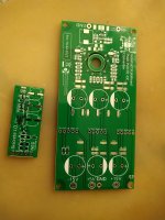
Connecting pcb to main board is as like on picture!
Connecting pcb to main board is as like on picture!
Attachments
Answered my question, don't know how I missed it.But in post #7 you said,
"The opamp is supplied from the output voltage so there's your limit as far as output voltage is concerned. I think max 44V (+/-22V) is the limit for available opamps, in that case you don't want to go higher than 40V or so."
Somebody will need +15V reg? I calculated resistor values and simulated circuit, its very similar as +5V reg. You should use pcb from post 3206, only resistor values need to be changed & zener Z1, see picture from attachment. I have made negative reg pcb, if you need it let me know!
Attachments
There is a way to obtain 50V? For Pass FE 2022.You can always lower the opamp supply of course.
Jan

I'm sure you can think of a few different ways to modify the diyAudio Store "Super Regulator" so it can accept 65VDC input and produce 50VDC output. But you will have to design the modifications and test them, yourself. Maybe simulation might be a useful tool for your design efforts; maybe not.
I have alternatives that will. I just wanted to use my stock of S/R boards. The usual problem of not having the means and time to deep dive into another new subject.I'm sure you can think of a few different ways to modify the diyAudio Store "Super Regulator" so it can accept 65VDC input and produce 50VDC output.
Thankyou
H.
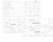
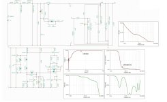
After testing circuit from post 3206 and 3210 in combination with push pull preregulator similar to one from post 3195, in next 30 days, this schematic from attachment would be the next level. Added inline filter, it will filter push pull regulator and in the same time we getting much smaler IN-OUT capacitors, better startup time, much better PSRR, SNR, noise, this looks phenomenal?
Attachments
Last edited:
I will share this with you in case everything work, including simple and amazing 900kHz self oscilating bombon push pull regulator suplied from 1A high voltage pre regulator. Isolated bombon regulator can give about stable 5W, hope enought for three J.D. regulators : ) Project is designed to supply discrete DSD dac with i/v, mfb, tone control, se to diff, it will consume about 50-100mA in total so I'm believing all will work good enought as I expect. I will show you result when I solder all, in case it work good you getting gerber, bom and instruction for small bombon torioid wiring. Booth projects including dsd dac will be soon open source for diy use!
Attachments
Last edited:
Dear All,
I need some help to debug a Negative Superreg at -15V.
I build 3 regulators for a dac that need +5V, +15V and -15V.
The +5V and +15V work at the first power up, absolutely stable, but I am not able to make the -15V working.
I recheck all the components, I changed the BC546, the LM369, the Zener 6,8V that I have available.
I do not have the AD825 so I install a OPA1641 that I have from another project but the result is the same so I reinstalled the AD825
I am sure I miss something very simple and I aid to ask for help for a so simple board but I am stacked...
I power up the board with a lab PSU and the Vout is following any change on Vin with more or less 1V difference
I take some measurement on the board referred to GND

Any support will be appreciate
Thanks and Regards,
Enrico
I need some help to debug a Negative Superreg at -15V.
I build 3 regulators for a dac that need +5V, +15V and -15V.
The +5V and +15V work at the first power up, absolutely stable, but I am not able to make the -15V working.
I recheck all the components, I changed the BC546, the LM369, the Zener 6,8V that I have available.
I do not have the AD825 so I install a OPA1641 that I have from another project but the result is the same so I reinstalled the AD825
I am sure I miss something very simple and I aid to ask for help for a so simple board but I am stacked...
I power up the board with a lab PSU and the Vout is following any change on Vin with more or less 1V difference
I take some measurement on the board referred to GND
Any support will be appreciate
Thanks and Regards,
Enrico
Thanks Savan but the pcb doesn’t allow to swap the pins in the opamps...Most probably you have swaped pin 2 and 3 of the opamp, try swap them.
Thanks tombo56.LED diode is put the wrong way and is reverse biased, conducting no current. Rotate it 180°.
The led was correct but I change it anyway with no luck.
- Home
- The diyAudio Store
- Super Regulator