there are links at the bottom of the schematics
Does a shunt regulator have any advantage over SR?
Some relevant discussion: https://www.diyaudio.com/community/threads/shunt-hv-vs-series-hv.376889/Does a shunt regulator have any advantage over SR?
Pay attention to the post #14 and what jackinny explains.
Some ten years ago I did tests of shunt vs series regulator in a digital environment (CS8414, PMD100, TDA1541,...) and then the ordinary shunt regulator that I made with noisy LM317 as CCS and AD711 op amp was better than SR. Since then I always use shunt reg for digital and SR for analog.Does a shunt regulator have any advantage over SR?
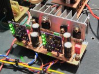
For the first time now I tried Walt's shunt regulator for analog, specifically for AD811 in my DAC and I can say that I am very satisfied, it is an improved version with Walt Jung low-noise references insted of LM329 and ADA4625-1 op-amps.
Attachments
I have, but not after a rectifier. My source is a 13V battery. The reason I used two stages was to feed both opamps with the 10V output of the first stage, because the 5V output of the second stage was too low for some of the opamps, which I wanted to try. The two-stage circuit also allows using a reference with a higher voltage than at the output. Finally this helps bootstrapping some low noise series references that don’t start in the single stage circuit.
I have not had any issues with two Suoer Regulators working sequentially. You can remove the input capacitor of the second stage, because it is in parallel with the output capacitor of the first stage, but it worked either way with 100uF Elna Silmic 2.
Oh, and also there is no need for the Zener and its filter capacitor at the opamp output of the second stage (to be precise, this is when you feed the second stage opamp from the first stage output / second stage input).
I used a negative board (in the positive output configuration) for the first stage, but there are many possible configurations depending on your objectives.
Last edited:
OK, so I now have two super regulators working in series: 32VDC raw into the first reg with 24 volts out into the second reg with 15 volts out to the load. What I did notice that with that 32 volts in, trying 20 volts out produced lots of overheating of the IC. 24 volts out cured that.
As to the sound, It sounds better to me. I'll leave it at that.
As to the sound, It sounds better to me. I'll leave it at that.
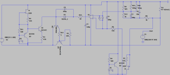
@tamra, you can connect GLED431 as they are connected in this scheme, it is a Walt Jung shunt regulator but the right side is identical to a series regulator.
Instead of 2SK3557 you can use 2SK246 or similar jfet. Instead of zener diodes for D2 and D7, you can also use a red LED.
I have a question about a high current version. Beacuse i could not cover a whole load from 0 to 5 A from a pass transistor driven directly from opamp, i decided to use Emitter Follower/Darlington to buffer. I simulated this version and it seems to work well.
I noticed however, that on the schematic from grunf, he uses his buffer transistor BEFORE zener // capacitor. I use it in classic darlington conf, i.e. with driver transistor after ther Zener.
The diffrence is the amount of current going through the 6,8V Zener and it`s parallel 100uF capacitor. In my version, the swing through the Zener is of 0,15 mA, whereas in Grunf`s version it`s in the range of 20mA.
What configuration is better for the speed, noise, or output impedance of the regulator, i.e. overall quality ?
Attachments
The Zener doesn’t significantly affect the speed, noise, or output impedance for several reasons, particularly because of the filtering capacitor. The current should be in the working range of the Zener. Check the data sheets for the test current.
While on this, what is the purpose of R8/C9 and how do you calculate the values?
Also, if your output is 20V, shouldn’t the Zener be closer to 11V than 6.8V?
While on this, what is the purpose of R8/C9 and how do you calculate the values?
Also, if your output is 20V, shouldn’t the Zener be closer to 11V than 6.8V?
Last edited:
R8/C9 on my schematic do the same what 220R/100pF did on original schematic for Super Regulator. I changed the voltage reference for 2,5V instead of 6,9V from LM329, hence i had to adjust the voltage divider from remote sense point. I run out of LM329 and went with GLED from Walt Jung with some mods (red led, bc559 instead of ESD unreliable ztx951 and jfet CCS to set up the current through the refererence to about 10-11 mA, split in half between bc559 and RLED).
I calculated the RC filter point from original schematic and recalculated (reduced) the value of the capacitor for higher resistor to stay more less in the same region of remote sense filtering.
After reading some more info about the optimal Zener current and lowest noise, i found that original 6,8V is the worst i could go with (highest noise). Also Zeners seem to like more current through them. I can change now for 12V in the same package, since i ordered the pcb already, and 12V according to Diode noise measurements from this forum is actually quiet. I should also burden the Zener (and opamp) with more current, and think about additional 1k resistor from output to the base of driver transistor KSA1381.
I considered once a string of 3-4 LED forward biased as supposedly quieter, but without darlington transistor, i had a swing of 5000mA/120beta= 0-42mA through them, and thought it to be too much, not to mention the parasitic photoresistor effect between blinking LEDs.
Now, in search of "absolute best", i consider using NiMH batteries to offset the output voltage of opamp. The offset is, according to the 4 original articles about the regulator, not that critical as long as it gives enough headroom from supply, i.e. could be 6,8V, 5V or 12V. I did run simulations with as little as 2,4V battery offset (2 x 1,2V NiMH cell) and with 25V input and 1V ripple, and load from 50mA to 6A, opamp seems to work fine. I aim for 18V output and did notice that regulator really needs at least 5V offset from the input to work well. Beacuse of wild mains voltage diffrencies (photovoltaics), i see from 213 to 253 V in my socket, and cannot go with the regular transformer and bridge rectifier. 2x 24VDC 10A SMPS i bought very cheap off ebay are surprisingly quiet under heavy load (my analog Tektronix barely triggers, i doubled checked agains other noisier SMPS), so 24-18-5V offset give me still 1 Volt of headroom for heavy choke coil filtering.
Last edited:
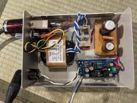

Congratulations @tamra ! I think you had an excellent idea, to make a DC umbilical cable with different connector styles on each end. XLR to the PSU, Barrel Jack to the ACP+ amplifier. This makes it more difficult to accidentally connect the wrong cable or the wrong piece of equipment.
@RickRay
I could see that after I posted.
Too late now, but it would have been a useful data point to have the "remote" sense connected from a "remote" regulator when general practice (and conventional wisdom?) is to locate the regulators as close as possible to the circuits being powered... and still employ the sense because it is integral to the operation of the regulator (per Jan). Just sayin'.
- Home
- The diyAudio Store
- Super Regulator