Yes, you can ask others to do a research and measurements on any idea that comes upon you mind. It is entirely another question if they have time or see there is any point in doing that.
BTW, if you haven’t noticed, Jan Didden terminated his membership here. Wonder why?
BTW, if you haven’t noticed, Jan Didden terminated his membership here. Wonder why?
You didn't read my post 2952, the LED reference is already finished and tested(even PCBs), I currently have 14 of them in my audio system from 2.5V to 9V, and I made four 16V for Hiraga 20W A-class and even a 180V version for HV regulator but with zener diodes because who would solder so many LEDs.The option to use series LEDs as references hasn't yet been quite analyzed in this forum. Least of all build an SR and measure it to see what you get. On simulations it seems to do fine, but noise is still an issue.
Pity Jan or Walt didn't bother to comment on it. At least to positively and definitely say why it's not a good option.
")
The LED version will be low noise and with the zener precise reference, I don't know when Walt will announce it yet, but I will give a hint here on the forum.
Attachments
OK, my pet hate is where someone asks in a thread, and then never comes back to update what solved the issue. So here goes:No capacitors are bypassed, load is a resistor right at the terminals. The PCB is v2.3 from the diyaudio store a few months back....
I will try swapping back in the OPA1611 with the cap on the power pins and see if it is stable with that. I originally had the OPA1611 soldered down to the smd pads, but the op27 is in a socket. So I will put the OPA1611 on an adaptor and see if it oscillates still.
Some decoupling (100uf) on pins 4/7 of the opamp solved the issue when using OPA1611. Once that was there, and the Panasonic caps were used instead of Wurth for C3/4 then there is no oscillation at loads I tested (up to 700mA).
So when I bought the boards from the store, I bought two sets. My order of some AD825 also came in today, so I went ahead and built up the second boards using the AD825. I kept the decoupling on the opamps as above and also the Panasonic caps. All went smoothly and no oscillation observed.
I have scanned through all the pages of this thread, and I didn't see anyone else doing that, maybe I just missed it. I did see it mentioned in the original linear audio articles.
So my learning from this includes:
- pay very careful attention to the C3/4/7/8.
- Add some decoupling under the board across the opamp power pins if you see oscillation.
- You cannot build this supply without an oscilloscope to check.
- You can run reference diodes in series if you have them - might affect ultimate performance of course.
- OP27, AD825, OPA1611 all will "work" but again undoubtedly there are performance differences in each.
I look forward to trying it out in circuit in the future.
best choice for C3/7 are Nichicon UKZ 100uF/25V as well as for C9/C10, for others Panasonic FC will be good and be careful with op amps , look at the input common-mode voltage range in DS, for example OP27 cannot work with 12V power supply and 10V reference ,AD825 is on the edge so that can also affect performance and stability
No, I didn't notice. Jan terminated his membership with DIYAudio or with this thread?BTW, if you haven’t noticed, Jan Didden terminated his membership here. Wonder why?
Did he said why he did that?
If I look at the schematic then I see there are C4 and C8 120uF caps close to opamp pins 4/7. Do I need to add another cap 100uF there straight to the between opamp pins 4/7 or C4 and C8 will do the job to use OPA1611?Some decoupling (100uf) on pins 4/7 of the opamp solved the issue when using OPA1611
Last edited:
I added them right across pins 4 and 7 of the opamp, but hey, they clearly aren't provided on these boards, so this was a patch to get mine to stop oscillating. I haven't seen anyone else doing this, so this is something odd with my build. This bothers me!If I look at the schematic then I see there are C4 and C8 120uF caps close to opamp pins 4/7. Do I need to add another cap 100uF there straight to the between opamp pins 4/7 or C4 and C8 will do the job to use OPA1611?
I don't know why you're all fixated on bipolar op amps ?
Because we are trying to follow the recommendations we see made by those who have built before, coupled with what available parts there are.... and in large part because we (I) don't know better.
This would be great info to have in the first post.best choice for C3/7 are Nichicon UKZ 100uF/25V as well as for C9/C10, for others Panasonic FC will be good and be careful with op amps , look at the input common-mode voltage range in DS, for example OP27 cannot work with 12V power supply and 10V reference ,AD825 is on the edge so that can also affect performance and stability
Hello everyone,
I have a quick design question. I'd like to use low noise series voltage references in the Super Regulator, but it is impossible on the negative side without modifying the circuit. The diagram on the left is the (highly simplified) negative Super Regulator where using a series reference instead of the zener is generally impossible. The diagram on the right is a modified (mirror flipped) circuit where a series reference can be used.
My question is if this modification will work and if any concerns exist with the modified circuit (performance, noise, etc.). I would appreciate any insight.
Thanks,
Alex
Last edited:
Thanks Rick, I am familiar with Jan’s article. My circuit above on the left is his negative circuit where a series reference cannot be used. The circuit on the right is modified to allow the use of a series reference. Please notice that the reference is connected to the inverting input if the opamp. So no change of the transistor flavor is needed.
If the objective for these caps is a low ESR, what is your opinion on using specialized low-ESR caps instead? UKZ are audio grade, but no audio signal passes through C3/7, which is just a filter of the reference noise. For example, this cap (Mfr. #: 870135675003) Wurth Elektronik 100u/35V has a 22mOhm ESR and fits the Super Regulator board by size. In contrast, UKZ do not have a specified ESR and generally are not considered a low-ESR caps. What do you think on this?best choice for C3/7 are Nichicon UKZ 100uF/25V
Please never mind. I see in Walt's article "An Improved Reference Filter for Audio Regulator" that the critical factor is not ESR, but the leakage current, which is substantially lower for UKZ. In this case, what about Nichicon UKL that have 5 times less DC leakage than UKZ?
Last edited:
If we look at this article then where the R1 resistor should be placed or changed to 5k ohm in this Super regulator schematic?Please never mind. I see in Walt's article "An Improved Reference Filter for Audio Regulator" that the critical factor is not ESR, but the leakage current, which is substantially lower for UKZ. In this case, what about Nichicon UKL that have 5 times less DC leakage than UKZ?
It is R4/R11 changed from 499 to 4.99k between the voltage reference and JFET opamp; C9/C10 must be Nichicon UKZ 100u and at least 25V. Also C3/C7 should be the same, although less critical. (My question above is if UKZ can be replaced by UKL.)
Last edited:
To be honest I have not tried the Nichicon UKL because regardless of the low leakage current it is still a standard capacitor. UKZ still has better performance and, according to measurements, low leakage current.Please never mind. I see in Walt's article "An Improved Reference Filter for Audio Regulator" that the critical factor is not ESR, but the leakage current, which is substantially lower for UKZ. In this case, what about Nichicon UKL that have 5 times less DC leakage than UKZ?
And as you ask about the UKL, I put a couple in a new order from Mouser, when they arrive I will let you know the test results.
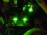
Success with dual boards.
+15.14v
-15.11v
Using a 35v center-tap transformer. Before the regulator boards, is a temporary (test) bridge rectifier and two 1000uf 35v smoothing caps to make + and - DC.
R7 and R14 = 1k
R6 and R13= 1.1k
6.9v vRef
Green LED
7.5v zener
AD817 opamps
(also works with NE5534's)
+15.14v
-15.11v
Using a 35v center-tap transformer. Before the regulator boards, is a temporary (test) bridge rectifier and two 1000uf 35v smoothing caps to make + and - DC.
R7 and R14 = 1k
R6 and R13= 1.1k
6.9v vRef
Green LED
7.5v zener
AD817 opamps
(also works with NE5534's)
Last edited:
- Home
- The diyAudio Store
- Super Regulator