I haven't used them yet but I have them for a couple of projects including a reworking of my Hafler DH-200.
Others will have to weigh in on their efficacy in this -- or any -- application. There are opinions all ways.
Same with snubbers on the transformer secondaries (which I think I'll install too).
Others will have to weigh in on their efficacy in this -- or any -- application. There are opinions all ways.
Same with snubbers on the transformer secondaries (which I think I'll install too).
this being in front of the Superreg, would switching to fast, soft recovery diode bridge even make any difference, on the outputs of the Superreg?
No
Same with snubbers on the transformer secondaries (which I think I'll install too).
Wouldn’t chokes be more effective?
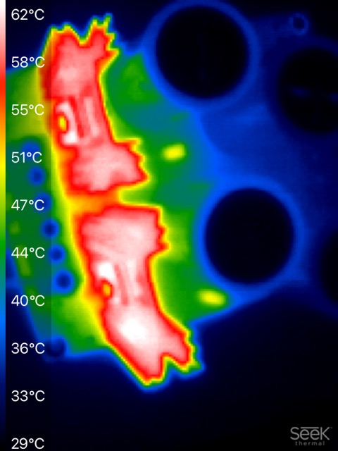
If your fast, soft recovery diodes happen to be Schottky, then you'll have less power to dissipate, smaller cheaper (or completely absent) heatsinks, and less heating of the nearby electrolytic caps. Here's a photo of a Schottky diode bridge (two diodes per heatsink, times 2 heatsinks) delivering >200 watts to a very large load resistor (8A , 28V). The hot diodes manage to warm up the nearby cylindrical caps. Electrolytics don't like that. It would be a lot worse if the diodes weren't Schottky.
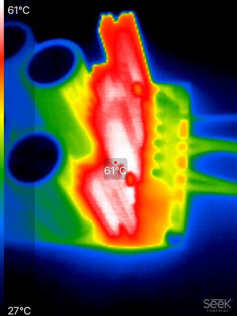
The camera feature "mark the hottest spot on the image" was enabled in the first picture, that's the red diamond inside the text box at the center.
_
The camera feature "mark the hottest spot on the image" was enabled in the first picture, that's the red diamond inside the text box at the center.
_
Last edited:
@safesphere
I'm planning to use those too per the suggestions made in Audio Amateur for the precursor of these regulators of Jan's.
https://refsnregs.waltjung.org/Regs_for_High_Perf_Audio_4.pdf
I'm planning to use those too per the suggestions made in Audio Amateur for the precursor of these regulators of Jan's.
https://refsnregs.waltjung.org/Regs_for_High_Perf_Audio_4.pdf
Attachments
Last edited:

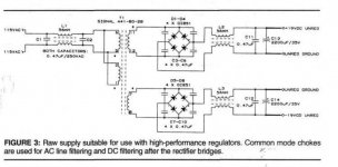
Rather than use the 4 large 0.47 bypass caps around the diodes shown in the Audio Amateur article it’s more effective, smaller (and cheaper) to leave them out and use Mark Johnson’s Quasimodo CRC snubber ( 0.01uf and 0.15uf +R) on each bridge.
The 0.47 caps, besides snubbing the diodes, will always be passing high frequency AC line noise past the diodes for the entire AC cycle.
The Quasimodo snubber more effectively reduces the ringing of the diodes during turn on/off and doesn’t feed power line noise past the diodes.
The 0.47 caps, besides snubbing the diodes, will always be passing high frequency AC line noise past the diodes for the entire AC cycle.
The Quasimodo snubber more effectively reduces the ringing of the diodes during turn on/off and doesn’t feed power line noise past the diodes.
Last edited:
I use common mode chokes in both AC line and DC supplies. You want damp the choke in DC supplies with a resistor in parallel with each winding of 10 to 20 times the DC resistance as a rough guideline. Also check that the load current is equal in DC chokes in both polarities, ( add resistance to the lower current draw to get the currents equal - the choke works best when equally loaded).
a greeting to all, a simple question to avoid mistakes .... what is the maximum VAC supported by Superreg in the version .. let's say .. "standard" sold on diyAudio store?
thank you all.
Giampiero
The superreg needs to be fed by DC, not AC.
Jan
OK, 22V is no problem, the opamp and series transistor and output elcaps can handle that.
Now, you probably want to use an input voltage between 24 and 28V, so you must use elcaps at the input rated for say 35V. The elcaps at the output side can be 25V.
But if you are going to order parts it is easiest to get 35V elcaps for all positions. And they are not critical, 100uF, 120uF, all fine. Don't spend a lot of money here.
Jan
I have been reading a lot about power supplies lately (still a noob, but starting to understand things ... a bit) and have been wondering if I could expect sonic benefits when using a Jung/Didden super regulator to replace an LM723/2N3055 based power supply for a pre amp?
I have v2.2 boards that I bought from the store some years ago but have not yet used.
For those that are interested, this is why I am considering it:
I have a Jeff Rowland Consummate preamp (1993) that I love. It was my main preamp and was working fine until a few years ago.
Not being in the US, and with taxes, freight, etc. being ridiculous, I did not send the unit for repair to Rowland but emailed Rowland to discover what could be the cause and if I could have it repaired locally. It took a while but eventually I was asked to test a few things and we discovered that for some reason I had DC on the output. The diagnosis was that the gain modules were defective as this is a common cause of DC on the output. Replacements were no longer available for this preamp that went out of production 28 years ago. Although replacements were no longer available, I kept the preamp in storage, hoping that one day I would be able to get it fixed.
About a year later I heard that Jeff had found some old replacement modules! I bought them and hoped everything would be fixed. I thought it had, and while sometimes (both with the new modules and my old modules!) the amp worked fine, at other times here was no sound at all or the dreaded DC on the output was back. Being unreliable and not wanting to damage my other equipment, the amp went back in storage. It made me question the original diagnosis.
At the time Jeff told me the gain modules hardly ever die, and to have two die at the same time was very strange. They can easily be broken if incorrectly installed on the header pins, but when the problems started my amp had not been openend for years, so that could not be the cause. Having bought working replacements and finding my problem has not gone away, I do not think the problem was the gain modules. I have since been wondering if the power supply could be the cause. Although it measured fine when I tested it some years ago (not under load), 28 year old electrolytic caps could be a problem just to name one possible cause.
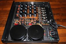
I have attached a photo of the (separate) power supply. It is rated as 2 x +21V/0.75A, 2 x -21V/0.75A and 2 x +9V/1.5A. It was designed to power a Consummate preamp as well as the optional Consummate phono stage (which I do not have). For this reason there are effectively 2 identical +/-21V and +9V power supplies in the enclosure.
Some people would grab the soldering iron and start replacing suspect parts, but limited mobility, limited experience and a software background means I try to figure out what is wrong before even thinking of trying to fix (and possibly wreck) the unit.
Studying the parts and pcb from the component side only (I have not even removed it from the enclosure) I have deduced the +/-21V power supplies are LM723 based with a 2N3055 as external npn pass transistor. The 9V seems to be more complex and also incorporates a TL7702B, but I do not think it has anything to do with the problem because I think it only controls relays, the remote receiver and the display.
To see if the preamp itself is OK and the problem really is the power supply, I could use lab psu's. I just need to figure out what connectors were used in the umbilical, as I would prefer not to modify the preamp itself. That however is not the reason for this post.
I wondered if an SR based psu would have sonic benefits over the LM723 based design. Your thoughts are appreciated.
I have v2.2 boards that I bought from the store some years ago but have not yet used.
For those that are interested, this is why I am considering it:
I have a Jeff Rowland Consummate preamp (1993) that I love. It was my main preamp and was working fine until a few years ago.
Not being in the US, and with taxes, freight, etc. being ridiculous, I did not send the unit for repair to Rowland but emailed Rowland to discover what could be the cause and if I could have it repaired locally. It took a while but eventually I was asked to test a few things and we discovered that for some reason I had DC on the output. The diagnosis was that the gain modules were defective as this is a common cause of DC on the output. Replacements were no longer available for this preamp that went out of production 28 years ago. Although replacements were no longer available, I kept the preamp in storage, hoping that one day I would be able to get it fixed.
About a year later I heard that Jeff had found some old replacement modules! I bought them and hoped everything would be fixed. I thought it had, and while sometimes (both with the new modules and my old modules!) the amp worked fine, at other times here was no sound at all or the dreaded DC on the output was back. Being unreliable and not wanting to damage my other equipment, the amp went back in storage. It made me question the original diagnosis.
At the time Jeff told me the gain modules hardly ever die, and to have two die at the same time was very strange. They can easily be broken if incorrectly installed on the header pins, but when the problems started my amp had not been openend for years, so that could not be the cause. Having bought working replacements and finding my problem has not gone away, I do not think the problem was the gain modules. I have since been wondering if the power supply could be the cause. Although it measured fine when I tested it some years ago (not under load), 28 year old electrolytic caps could be a problem just to name one possible cause.
I have attached a photo of the (separate) power supply. It is rated as 2 x +21V/0.75A, 2 x -21V/0.75A and 2 x +9V/1.5A. It was designed to power a Consummate preamp as well as the optional Consummate phono stage (which I do not have). For this reason there are effectively 2 identical +/-21V and +9V power supplies in the enclosure.
Some people would grab the soldering iron and start replacing suspect parts, but limited mobility, limited experience and a software background means I try to figure out what is wrong before even thinking of trying to fix (and possibly wreck) the unit.
Studying the parts and pcb from the component side only (I have not even removed it from the enclosure) I have deduced the +/-21V power supplies are LM723 based with a 2N3055 as external npn pass transistor. The 9V seems to be more complex and also incorporates a TL7702B, but I do not think it has anything to do with the problem because I think it only controls relays, the remote receiver and the display.
To see if the preamp itself is OK and the problem really is the power supply, I could use lab psu's. I just need to figure out what connectors were used in the umbilical, as I would prefer not to modify the preamp itself. That however is not the reason for this post.
I wondered if an SR based psu would have sonic benefits over the LM723 based design. Your thoughts are appreciated.
Attachments
- Home
- The diyAudio Store
- Super Regulator