Sorry to jump in with a basic question this far in the thread.. but I just discovered the thread today and wanted to implement the super reg as my first real DIY " newbee audio project" (with no magic smoke if possible)
I would like to replace my squeezebox touch PSU (1.5A) and the +5v on my CD Pro 2 Drive (1.5A)......
a. I have some AD797AN available..is a good choice for U1?
b...Also.... as I only require 2 +5 v PSUS can the negative side of the PCB be adapted for positive operation? (save buying 2 sets of PCBS?)
c... and..I also have to hand some BC550C but I don't think that's up to the pass transistor job is it?
Thanks for putting up with the questions this late on...I tried doing the math's by looking at the past threads but my results way off (I think?)
regards
Johnny
Sorry for the late reply:
If you have a transformer with two separate secondaries, you can use one secondary for the pos reg and one for the neg reg. Then you connect the output of the neg reg to ground, and the 'ground' end of the neg reg become another pos regulated output. Be sure that none of the 'ground' connections of the neg reg is connected to ground but instead to the 'pos regulated output',
jan
Anyone a circuit idea for a power LED indicator, LED output is faint when power supply is delivering standby current to the external device, and bright when the external device is on, requesting more current from PS?
Eddy, depends a bit on the difference between no-load and load current. How much is it?
Jan
Anyone a circuit idea for a power LED indicator, LED output is faint when power supply is delivering standby current to the external device, and bright when the external device is on, requesting more current from PS?
A microcontroller with onboard ADC and nonvolatile memory ("flash" or "EEPROM") could do this, and in fact it could learn the different supply currents that occur when the powered equipment runs in its various operating modes. Merely a small matter of software
Hi Jan, standby current is 100mA, 'on' is 440mA @18V.Eddy, depends a bit on the difference between no-load and load current. How much is it?
Jan
I've put a lm317 circuit in front of the super reg. Maybe I can do something between the 2 reg's..
ps: great superreg pcb quality!
- It's possible to use the negative PS board, but you have to invert all polarized components on the board. Also you have to cut all the tracks to the opamp en swap input pins, and also voltage pins.
- For 1.5 amps output, most likely you have to tweak the current source (R1). Be careful not to overload the opamp. I've increased to current source from 4mA to 7.5mA to get 1A out with some margin. A larger heatsink could be necessary.
..the opamp en swap input pins, and also voltage pins.... No that's not true. Only the supply pins, 4 and 7.
I do appreciate the interest for different output voltages. But to be honest, I spend several days to write up these things and trying to be as clear as possible, to help prospective builders to be successful.
I do NOT make any money from this, not a penny.
I do not always have time to redo all this for all individual cases, and would recommend to read the article.
It is really very easy, and if you spend a few minutes you will be able to customise this to your hearts' extend, rather than having to beg someone else and then waiting impatiently until anybody takes the trouble to check it out for you.
This IS diy...
Jan
Hi Jan, standby current is 100mA, 'on' is 440mA @18V.
I've put a lm317 circuit in front of the super reg. Maybe I can do something between the 2 reg's..
ps: great superreg pcb quality!
A simple solution would be to have a resistor and an LED on the input of the reg for standby indication.
Then in series with the prereg you do a small resistor that drops about 0.6V at 300mA, and use the resistor between E and B of a transistor, using the C to drive another resistor with current into the same LED. That will give you extra luminosity on the LED when load exceeds 300mA.
Jan
To increase the maximum output current, modify the design.
One possible design mod would be to substitute a high current depletion mode MOSFET + plenty big heatsink, for the series pass transistor. Perhaps something like the IXTP3N100.
Another possible design modification would be a 2-transistor replacement for the D44H11. You could consider a Complementary Feedback Pair ("Sziklai Pair"), a Darlington pair, or a depletion MOSFET-BJT pair. The Supertex DN4250 depletion MOSFET that Walt Jung advocates, might be an especially good choice.
A third possible design modification would be to use the Jung/Didden SuperRegulator with a conventional PNP (on big heatsink) current booster. The SuperReg supplies the first 75mA and the PNP supplies all the rest. Chose R1 = (VBE / 75mA) in the generalized schematic below.
In each case, your designer would want to verify that the modified circuit was unconditionally stable, and that its regulation characteristics (output impedance, line regulation, load regulation, noise, etc) remained excellent.
An externally hosted image should be here but it was not working when we last tested it.
Hi Mark
I am interested in trying the 1st and the 3rd suggestions.
However, before I plug a MOSFET into the regulator,
I need some clarification and advice.
Q1. Most MOSFETs have capacitance in the range of nF,
will it cause instability to the opamp as it has to drive a large capacitive load?
Q2. I have looked up some information from some MOSFETs datasheet,
in particular, I focus on parameters like max I, Vgs, Rds, Tr, Pdis and various Cs.
I look for low Tr, Vgs and large Pdis. Are there any other important parameter that I missed? (IXTP3N100 looks pretty good to me, what about IRLZ24N or IRF530N, I have plenty 530s at home)
Q3. I am confused that whether I need and n-channel or a p-channel MOSFET?
The Jung/Didden Super Regulator is a sophisticated, high performance, marginally stable circuit that is prone to oscillation, even when constructed by expert designers who have lots of experience. I recommend that you DON'T try to modify it unless you really know what you're doing.
If you can duplicate jackinnj's simulated Bode plot of the unmodified Super Regulator (in post#177), then you might have a chance of succeeding. If not, I recommend you don't attempt to modify the SR. It won't work and you'll be unhappy.
If you can duplicate jackinnj's simulated Bode plot of the unmodified Super Regulator (in post#177), then you might have a chance of succeeding. If not, I recommend you don't attempt to modify the SR. It won't work and you'll be unhappy.
I think Mark's warning is appropriate. Although I would probably not agree to 'marginal stability', the design is highly optimized for very high performance. For example, replacing the output electrolytic with a boutique film cap will modify the loop gain and can induce oscillations.
I have build dozens of these circuits with no problems, but some of the changes discussed above are quite drastic and you are on your own on those.
If there is enough interest, I could develop a high-current version....
Jan
I have build dozens of these circuits with no problems, but some of the changes discussed above are quite drastic and you are on your own on those.
If there is enough interest, I could develop a high-current version....
Jan
Mark & Jan
Thank you for the cautious advice.
I need some time to figure out and work on the subcircuit and models in LTSpice.
I will start from here and plug in the necessary components:
http://www.diyaudio.com/forums/blog...level-audio-part-vi-jung-super-regulator.html
Thank you for the cautious advice.
I need some time to figure out and work on the subcircuit and models in LTSpice.
I will start from here and plug in the necessary components:
http://www.diyaudio.com/forums/blog...level-audio-part-vi-jung-super-regulator.html
Sorry for posting a wrong plot.
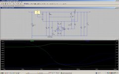
I re-ran the simulation (some resistor values in RJM's blog are different from Jung's 2000 article). I plugged the values show in the article into the schematic. It seems that there is something wrong around 1~2kHz if AD797 is used. For some MOSFETs, simulation cannot be run with AD797.
If replaced by OPA134, the plot looks more stable but the performance at low frequency is ...
Attachments
Last edited:
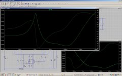
Here are some plots of the Jung Regulator with AD797:
and
The Z-out graph is the best i was able to measure in the very low end. Impedance in the vicinity of a micro-Ohm is not easy to measure.
An externally hosted image should be here but it was not working when we last tested it.
and
An externally hosted image should be here but it was not working when we last tested it.
The Z-out graph is the best i was able to measure in the very low end. Impedance in the vicinity of a micro-Ohm is not easy to measure.
Sorry for posting a wrong plot.
I re-ran the simulation (some resistor values in RJM's blog are different from Jung's 2000 article). I plugged the values show in the article into the schematic. It seems that there is something wrong around 1~2kHz if AD797 is used. For some MOSFETs, simulation cannot be run with AD797.
If replaced by OPA134, the plot looks more stable but the performance at low frequency is ...
The 797 is a somewhat different opamp from 'the others'. For one thing, it has an internal neutralisation loop based, iirc, on positive feedback. I don't know how accurate this is reflected in the spice model.
I do remember that the 797 was harder to stabilise in a practical superreg and both Walt and I eventually recommended other opamps for the design.
Jan
- Home
- The diyAudio Store
- Super Regulator