Is there a build guide for the V3 board?
I went back to V2 forum and the link there goes to a 'Class AB Amp' PDF - not the soft start.
The V1 build referenced a few pages back (from Feb 2019) results in " 404 Page Not Found'.
In short, what I'm looking for is the 'function' of 'Live SW1' vs SW2 at this stage
I'm assuming that 'Live SW1' is just an 'on-board' connector to the mains and is also used as the output (i.e. dual connectors) to the amp on/off switch that's output goes to SW2 to power the board? (The line Neural going direct to the board)
But I could be wrong.
In some countries I think that the on/off power switch needs to be dual pole (live and neutral) so the 'Live SW1' in this case would be superfluous and the amp on/off switch would feed both line (SW2) and Neutral on the board?
Polsol, see the three previous posts between MPA and myself concerning the function of the mains power inputs. I’ve attached the V1 build guide (it was somewhere in the diyAudio forums). There was no up-to-date-V3 build guide I could find. The important thing in the guide to look at is the section on "Ideas and Alternatives" for choices of the resistors and the one capacitor depending on your mains voltage (since I have 120V mains I chose 120R for R3-6 and 0.68 uF for C1). I also had to order a G5LE-14-CF 24VDC relay since the "G5LA" version is no longer available. To date I (& MPA) have not gotten a definite answer concerning the importance of using Line/SW1 over SW2 if you already have a power switch for your amp.
Attachments
Hi Turion64,
Yes I do have thanks - and the PCB is already populated with the suggested values.
BTW in SA we run at 230V (when we have electricity that is).
My biggest problem is understanding the purpose of C1 between SW1 and SW2?
I have a Shaffner combined On/Off switch, fuse and RF filter PEM on the rear panel and would have just connected the switch 'Line out' to Pwr_Sw 2 and Neutral to neutral on the PCB, and just left PWR_Sw 1 'out of the equation'.
At this stage I'm dispensing with a separate (additional power) switch on the front panel.
Thanks for your help/interest.
C1 is necessary if you use both SW1 & SW2 as intended. I skipped both C1 and the use of SW1 and took the mains outputs from my case switch directly to Neutral and SW2. Everything works fine but the soft start is too fast to observe with a multimeter (in my observations).
Pete
Pete
Polsol: that is correct, C2 on Version 3 board. I couldn’t (casually) notice any difference between the time the relays close when C2 was at 1 uF versus 0.68 uF (for 120V mains). It’s really fast and I don’t have anything more than a multimeter to observe responses.
the C2 limits the current that the relay coils needed...so if your relay coil had lower dc resistance, you may need a higher value, say 1ufd, than if the relay coil is higher...
the dc filter cap value determines the dalay, the higher the value, the longer delay...
how much delay?
transient take about 5 cycles or thereabouts to die down, for a 60hz line, that is 5/60, or about 83 msecs...
that is almost right after you flick the switch...
any resistance in series with your traffo primary limit turn on currents..
Thanks all for your input.
I ran an LTSpice simulation on the circuit (Omron G5LE-1-E DC24 relay with 1k44 coil resistance) and obtained the following values (using 325V Peak, 50Hz, R2 = 1Meg):
Circuit 'as is' C2 = 1uF, Rise time to 24V ± 500 ms
C2 @ 680nF, Rise time to 24V = ± 900 ms
C2 @ 470nF, Rise time to 24V = ± 2,500 ms
Changed C3 from 1,000 uF to 2,200 uF, Rise time to 24V = ± 1,100 ms
Of course this all depends if the relay actually latches up at 24V but I guess it would be at some lower value (latching time is 10ms) - and my Spice simulation being correct.
I'll try first with C2 as a 1uF capacitor and then adjust if necessary.
Hi Truin64,
No problem, I normally do run a spice simulation on a circuit - but not always when I'm lazy and the design is from a reputable source - unless I hit problems in getting the circuit to work.
And I hadn't initially run Spice in this one.
I'm an industrial chemist so my knowledge of electrical circuits is from high school, physics 1 at Uni and some reading.
From memory, these types of circuit are to prevent:
1. The initial inrush current from tripping circuit breakers.
2. To prevent blowing the fuses within the amp itself.
IRO (2), the ratings of the fuses should be set just above the expected max current of the amp. If this is done, and the inrush current is high at switch on, then one is likely to continuously blow the fuses. Setting the fuse values too high to negate inrush current means that the amp could draw too much current (e.g. with a short circuit) and cause a fire before the fuses blow.
3. Yes, I guess rapid voltage/current increases are not good for components either, certainly not good for the old incandescent lamps that used to fail on 'switch on'.
The inrush current will be high if the amount of capacitance in the PSU is high.
Anyway, that's my take. If I'm wrong then hopefully someone will correct me.
Enjoy the weekend.
Thank you for that polsol! I guess the question at hand (for the electronics knowledgeable) is what is an appropriate delay to avoid current inrush’s damaging influences on the components downstream?
first, the switch contacts will be safe from pitting due to high currents when not using the soft start circuit.
second, you can use smaller sized fuses that you can not use otherwise.
third, you can use smaller ampere rated switches, i.e. 16A without to 6A.
fourth, since starting current will be small the stress on the power traffos will be smaller, for EI's you may hear a thud, for toroid, core saturation is averted..
effects on downstream components, i am not so sure....
invalid parts in the BOM…
Hi friends
I was collecting the parts for the softitart/speaker-protection.
Some parts seem to be "end-of-lifed". Both the speaker-delay and the soft-start's BOM are concerned. I threw both in here out of laziness, pardon...
It's (softstart):
D1, D2, D3, D4 1N4007 Rectifier 1000Vr 1A 512-1N4007
and (speaker delay):
K1, K2 Relay Relay SPDT 5VDC 72mA 653-G5LA-14-CF-DC5
K1, K2 Relay Relay SPDT 12VDC 30mA 653-G5LA-14-CF-DC12
What can I substitute them with?
Thank you!
david


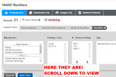
Figure_1
Figure_2
Figure_3
_
Thank you Mark.
It is a bit embarrassing having the solution right there...
Now there's just the relays left, not sure on those (mouser's proposed alternative seems to have a different size)

will look further soon.
- Home
- The diyAudio Store
- Power Supply Soft Start Board (V3)