Finally got around to building the soft start board. 
I had ordered the parts back in late May, and the parts bag has been sitting on the bench since then.
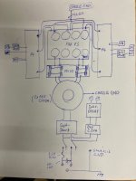
I am going to use it to power the 400VA transformer in my DIY Linear PSU, shown in the second image. It is still in the prototyping stage but with winter approaching I should have more time to work on my projects.
Initial testing look pretty promising. In case you are wondering I 3D printed a standoff as I was uncomfortable with the 120V on the traces along the underside of the soft-start board being so close to the metal chassis insert.
For any wondering I did end up using the Panasonic relay I was inquiring about above and it works great.


I had ordered the parts back in late May, and the parts bag has been sitting on the bench since then.
I am going to use it to power the 400VA transformer in my DIY Linear PSU, shown in the second image. It is still in the prototyping stage but with winter approaching I should have more time to work on my projects.
Initial testing look pretty promising. In case you are wondering I 3D printed a standoff as I was uncomfortable with the 120V on the traces along the underside of the soft-start board being so close to the metal chassis insert.
For any wondering I did end up using the Panasonic relay I was inquiring about above and it works great.
Last edited:
Hello , could you check my speaker protection board connection. Blue and brown to 12 VAC transformator, yellow to PSu ground. In this configuration delay works good but i Don't know if dc protection is also OK, because I did test with 1,5V battery ( + to IN on board and - to chassis) and relay did not disconnect speakers. Thanks for help in advance

Cross posted in Speaker protection thread as well.
Started populating soft and speaker protection board. Have some questions
Soft Start Board - I am building monoblocks so have 2 boards and 2 transformers. Now in addition I have 24VAC Antec small transformers for the speaker protection. So can I connect a 500VA transformer and this little 24VAC transformer in parallel to the soft start board? Since the second transformer is low VA and used for speaker protection can I just wire it directly to the same fused mains?
Speaker protection - I have two boards but looking to use only one side as its mono block. Should I just populate everything and use only one channel? Or can I omit few parts?
Thanks in advance.
Installing Soft Start in Pass Clones A la 6L6
After combing through this thread, I am still unsure of the most expedient and safe manner of adding the Soft Start board to existing F5, F6, and Aleph J chassis. I have followed the build guides from 6L6 using the 400U Deluxe chassis and Rear Panel package. Nothing fancy in the builds or components, and trying to stay loyal to the latest BOMs.
Attached are three diagrams to illustrate my questions (I need pictures):
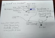
#1 is the current "standard 6L6" AC mains input the DIYAudio V3 power supply board. This uses the Schurter 4303.6090 IEC Power Entry module with 2 fuses and a line 2-pole switch.
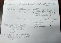
#2 is what I think is the most efficient addition of the Soft Start board to #1.
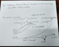
#3 is what I hope is an appropriate addition of a front panel switch to #2, without changing the Schurter IEC.
Hence,
#1 uses a barrier strip with CL-60 and X1/Y1 resistors for electrical safety, and the mains earth ground connected to a star ground djoining the transformer ground and a ceramic block with another CL-60 is connected to the ground of the power supply board.
#2 omits the barrier strip and resistors, the AC line is directly attached to SW2 input and the C1 resistor between SW1/Line and SW2 is removed. The star ground is still in place with the CL-60 connected to the PSB and the transformer. The SS board effectively replaces the barrier strip complex.
#3 is assuming #2 is appropriate and inserts a front panel switch. The AC mains line attaches to SW1/Line and an additional connection from this goes to a single pole single throw front panel switch. The other pole is connected to SW2 and C1 is populated. The same star grounding scheme is retained.
There are versions where the CL-60 is attached to the PCB ground and chassis directly and I think the transformer ground is connected to the chassis (I wish I had an image of this)
Am I on track?
Thanks JCB
After combing through this thread, I am still unsure of the most expedient and safe manner of adding the Soft Start board to existing F5, F6, and Aleph J chassis. I have followed the build guides from 6L6 using the 400U Deluxe chassis and Rear Panel package. Nothing fancy in the builds or components, and trying to stay loyal to the latest BOMs.
Attached are three diagrams to illustrate my questions (I need pictures):
#1 is the current "standard 6L6" AC mains input the DIYAudio V3 power supply board. This uses the Schurter 4303.6090 IEC Power Entry module with 2 fuses and a line 2-pole switch.
#2 is what I think is the most efficient addition of the Soft Start board to #1.
#3 is what I hope is an appropriate addition of a front panel switch to #2, without changing the Schurter IEC.
Hence,
#1 uses a barrier strip with CL-60 and X1/Y1 resistors for electrical safety, and the mains earth ground connected to a star ground djoining the transformer ground and a ceramic block with another CL-60 is connected to the ground of the power supply board.
#2 omits the barrier strip and resistors, the AC line is directly attached to SW2 input and the C1 resistor between SW1/Line and SW2 is removed. The star ground is still in place with the CL-60 connected to the PSB and the transformer. The SS board effectively replaces the barrier strip complex.
#3 is assuming #2 is appropriate and inserts a front panel switch. The AC mains line attaches to SW1/Line and an additional connection from this goes to a single pole single throw front panel switch. The other pole is connected to SW2 and C1 is populated. The same star grounding scheme is retained.
There are versions where the CL-60 is attached to the PCB ground and chassis directly and I think the transformer ground is connected to the chassis (I wish I had an image of this)
Am I on track?
Thanks JCB