hello tricksters, 24VAC is about the right voltage for the 2x 12VDC relays that you have.
if your main amplifier transformer has anything in the vicinity of 24VAC, you can take wires from your main transformer before rectification. And save the existing nice transformer for a nice headphone / pre-amp project.
if your main amplifier transformer has anything in the vicinity of 24VAC, you can take wires from your main transformer before rectification. And save the existing nice transformer for a nice headphone / pre-amp project.
Last edited:
The main transformer is a 500VA with 2x18V secondaries. I think I will buy another transformer with a single 24V secondary. 20VA / W
A 24 volt winding will generate nearly 35 volts DC. Your 18 volt (22 volts at light load) one generates over 30 volts. The design of the circuit and the low value of reservoir cap means the DC is not clean but the average DC voltage when your 400 ohm coils energise would be around 26 to 27 volts which is fine.
If you attach the ac input lead of the speaker protector to the correct phase of the positive supply on the exsisting 18 volt transformer . You will get 24 volts dc minus the voltage drop imposed by D4. I have used this method on several amplifiers wit great success.
Attachments
(Mooly). I used the components listed in Bom Version 3.0.2
That seems to be the version I had set up. Your nominally 18 volt transformer should be fine and at light loading you have measured the output at closer to 22 volts.
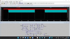
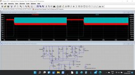
This is with 18 volt and then 22 volt AC applied. I've only shown the supply voltage generated and the relay current. When the relay energises the reservoir cap is at the higher rail voltage and only when energised does the voltage fall. That is a well known technique for reducing relay coil power dissipation. Once a relay has pulled in it will 'hold' on voltages down to around 30% of the coil rating.
Attachments
If you attach the ac input lead of the speaker protector to the correct phase of the positive supply on the exsisting 18 volt transformer . You will get 24 volts dc minus the voltage drop imposed by D4. I have used this method on several amplifiers wit great success.
It's a good idea to keep in mind.

That seems to be the version I had set up. Your nominally 18 volt transformer should be fine and at light loading you have measured the output at closer to 22 volts.
This is with 18 volt and then 22 volt AC applied. I've only shown the supply voltage generated and the relay current. When the relay energises the reservoir cap is at the higher rail voltage and only when energised does the voltage fall. That is a well known technique for reducing relay coil power dissipation. Once a relay has pulled in it will 'hold' on voltages down to around 30% of the coil rating.
I will try as soon as I can complete the board.
Speaker turn on delay (V3)
Can anyone tell me where a current build guide is for the version 3 board?
All I could find is (V1)
https://www.diyaudio.com/media/build-guides/diyaudio-speakerprotector-build-guide-v1.0.pdf
Anyone
Thanks
Scott
Can anyone tell me where a current build guide is for the version 3 board?
All I could find is (V1)
https://www.diyaudio.com/media/build-guides/diyaudio-speakerprotector-build-guide-v1.0.pdf
Anyone
Thanks
Scott
OK, it's straight forward, just use the BOM... Only thing that hurt my head is the Green and Red LED VIAs on the board. Normally a square VIA is + like for polarized caps but on this board for LED1 and LED2, the square VIA is the Neg side of the LED... Then I had to double check the spots for the caps to make sure they are correct, which they are...Yes I see the flat spot for the LED on the silkscreen but still...
OK, it's straight forward, just use the BOM... Only thing that hurt my head is the Green and Red LED VIAs on the board. Normally a square VIA is + like for polarized caps but on this board for LED1 and LED2, the square VIA is the Neg side of the LED... Then I had to double check the spots for the caps to make sure they are correct, which they are...Yes I see the flat spot for the LED on the silkscreen but still...
Yeah, the LED placements were a bit of an annoyance, true.
Hi all, 'just looking for a bit of help here please.
I have built this board and can confirm it is working on the test bench following instructions from the build guide, however I'm having an issue when installed in an F5.
Connecting the speaker O/P of the F5 to the speaker protect board will put the board into protect mode.
I am powering the board from one 18VAC winding direct from a transformer, either the one in the chassis or an external one and have the same result.
DC O/P from the F5 speaker wire measured with a DMM is in the order of few mV's.
Has anyone seen this issue or can point me a direction to fault find.
Cheers,
Simon
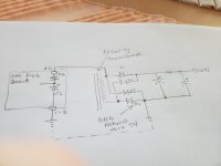
The speaker protect board is not referenced to ground. Only AC from the transformer and the speaker wire is connected. My question is how do I reference the board to ground, where do I attach the ground to the board, surly not where the AC is connected to the board (there is a g symbol there as well as a +be) marked same position as to AC in.
The ground point of the protection board must be connected to the ground point of the main amplifier.
(It is a bit like you connecting just the inner lead of an RCA connector between CD player and amp and saying all you get is a loud hum... the circuit is incomplete)
Because we are unsure exactly how you have configured your power supplies I would suggest first making the connection via a 100 ohm half watt resistor and checking that all is OK. It may well work with just that anyway. If all is OK and the resistor doesn't get hot then try a direct connection. If that is OK then all good. If it introduces any hum then try going back to a low value resistor to link the grounds such as a 4.7 or 10 ohm.
 that's good.
- Home
- The diyAudio Store
- Speaker Turn On Delay and DC Protector Board Set (V3)