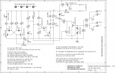
I was wondering if a schematic with some info regarding various attributes of the design can be posted, which will help new comers. It will also have some general info on tweaking to suit the taste / trouble shoot.
If this is not required/ deemed appropriate, request mods to delete this post.
regards
prasi
If this is not required/ deemed appropriate, request mods to delete this post.
regards
prasi
Attachments
Thanks MLE,
Nothing has been said, so I guess its ok for the schematic post.
But I feel its high time DIYA brings out / implements a SSR protect in the store design similar to Bonsai article.http://hifisonix.com/wordpress/wp-content/uploads/2013/01/Simple_solid_state_relay_Updated.pdf Configurable with just a single resistor for different voltages.
Last edited:
Probably so, an easy to implement/adjust jig would indeed be very nice...
but I must admit that this surpasses my knowledge. I couldn't say which is better (I couldn't even tell if a SSR is good at all)... I'm relying on the community (and trust 'our' collective intelligence, as much as the ingenuity of individuals like Salas, Mark, many others and you") ).
).
but I must admit that this surpasses my knowledge. I couldn't say which is better (I couldn't even tell if a SSR is good at all)... I'm relying on the community (and trust 'our' collective intelligence, as much as the ingenuity of individuals like Salas, Mark, many others and you
). . Can some expert take a look and suggest?
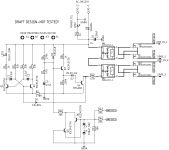
One thought and I don't know how this would play out in practice...
The PSU by design has a small time constant (the 220uF) and that means the ripple is high. That ripple has no effect on a relay but would it alter in any way the conductivity of the FET's by the fact the LED's in the photovoltaic couplers have this current superimposed on them?
It may well be an absolute non problem but maybe something that should be tested for real to be sure. It should be easy to detect by passing a small DC current through the FET relay and into a resistor and monitoring the voltage across the resistor for any modulation by the ripple.
The lower the LED current and the lower the supply ripple but also the time constant is altered as well so the overall circuit behaviour needs checking under those conditions as well.
I do like SSR's though
Yes, something like that or maybe even simpler given the low current requirements of the couplers. A Zener shunt regulator could work if scaled correctly or maybe just a constant current feed to the coupler LED (single JFET).
And it may well be a non issue that doesn't need anything... it just needs proving one way or the other first.
And it may well be a non issue that doesn't need anything... it just needs proving one way or the other first.
AC loss detection..
Thanks for the schematic, Does this schematic have AC loss detection for disconnecting speakers to avoid switch off thump?
Thanks and regards,
Sumesh
Thanks for the schematic, Does this schematic have AC loss detection for disconnecting speakers to avoid switch off thump?
Thanks and regards,
Sumesh
I was wondering if a schematic with some info regarding various attributes of the design can be posted, which will help new comers. It will also have some general info on tweaking to suit the taste / trouble shoot.
If this is not required/ deemed appropriate, request mods to delete this post.
regards
prasi
If you are worried about faster trip, refer the following post
Speaker Turn On Delay and DC Protector Board Set (V3)
Speaker Turn On Delay and DC Protector Board Set (V3)
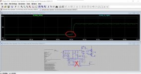
relays open after ~2.8 sec
8V 1.9A doesn't trip...
Is s Prasi's pcb on the way?If you are worried about faster trip, refer the following post
Speaker Turn On Delay and DC Protector Board Set (V3)
Those who have built the store pcb using using the bom G5LE/G5LA relay, if you want experiment using SS relay as a drop-in replacement , I have posted the design/ gerbers here in the following thread.
Output Relays
Output Relays
This is fascinating, as most of your projects are, Prasi!
If I was to try this and swap/drop in, would I have ...
a better jig? (Is s SS-relay mo' secure?), or would it rather be for the fun of building/experimenting, and "exoticity"?
And, does a SS-relay behave the same way with the same parts or do I have to change something in the neighborhood?
Thank you
david
Hi David,
You need to read this and see the videos Speaker DC protection with relays
EMR are never safe if you want to protect your precious speakers.
There is a long discussion here with various ideas Output Relays
pretty long thread , but I settled on Bonsai's idea / write up. http://hifisonix.com/wordpress/wp-content/uploads/2013/01/Simple_solid_state_relay_Updated.pdf
SSR will switch on and off all day long with no deterioration in performance and is much much much faster in switching than EMR., there is nothing fancy / exotic here , just to find a most reliable solution for speaker protection.
It will be a drop in replacement as the outline is same as G5L relay or finder relays ( http://www.farnell.com/datasheets/51058.pdf ).
In my main amp which running on P3A, I have the store protection design , (I etched my own boards). Every time I switch it on I cringe a bit because I don't know when it will be at fault and relays will weld together and burn my DIY floor standing speakers which I had made with lot of efforts and lot of money.
So I have already ordered the PCB, to have enough for 40 SSR drop-in relays. I have placed order for VOM1271T . I already have to-220 mosfets with 120V VDS , 5.8mOhm RDS on and ID of 112 amps or so.
So, PCB are cheap/ VOM costs about 3 USD/ Mosfets cost about 3 USD for 2 nos. , so pretty cheap overall, so nothing wrong in experimentation with proven design.
The .asc file is attached.
Hello Mooly,
Thanks for the sim file.
Using the same, I have incorporated the VOM1271 model and default mosfet models from spice. (dont know if this is correct).
Since I know very little about spice, I want to compare the off times of the relay versus the SSR. Could you help me in setting the sim file up properly for simulation and how to look for switch of times.
I have attached the zip file containing the spice sim file and the sub circuit of VOM1271.
regards
prasi
Attachments
It looks OK although the sim needs your specific symbol you created to run. That makes little difference though, the circuit as is takes about 23ms to trigger because of the R/C delay on the offset detector.
Attachments
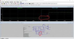
Thank you , so it works. Like you had said previously decreasing 330uF to 220u might speed up things a bit to 10ms.
Also looks like it will as drop in replacement without having the need to change anything.
For the symbol, I used autogeneration as described here https://www.ieee.li/pdf/viewgraphs/ltspice_creating_a_schematic_symbol.pdf
I dont know how to share symbols along with spice file, so I shared the sub circuit.
Once again thanks for your help.
The Auto Generated symbols in LTXVII are found under the Lib folder that LT places in the LT folder in documents. They can be copied and so on as needed.
The SSR should be a direct replacement, I did that same thing here. Post #260 and post #277 showing the on and off times of a real SSR:
Output Relays
Output Relays
The SSR should be a direct replacement, I did that same thing here. Post #260 and post #277 showing the on and off times of a real SSR:
Output Relays
Output Relays
- Home
- The diyAudio Store
- Speaker Turn On Delay and DC Protector Board Set (V3)