Hieroglyphs, circuits can look a bit like that sometimes  So are we saying it all works OK?
You could try ever lower battery voltages (such as putting a 2k preset across the battery and getting a variable voltage) and see what voltage yours trips at.
I found the PDF circuit easy to follow. Perhaps adding a new section on testing and also how to tweak it might be worthwhile as well... good thinking.
So are we saying it all works OK?You could try ever lower battery voltages (such as putting a 2k preset across the battery and getting a variable voltage) and see what voltage yours trips at.
I found the PDF circuit easy to follow. Perhaps adding a new section on testing and also how to tweak it might be worthwhile as well... good thinking.
Attachments
So are we saying it all works OK?
...adding a new section on testing and also how to tweak it might be worthwhile as well... good thinking.
Yes, I‘d say it passed the tests flawlessly.
... You made my day, thank you for your guidance, patience, evedyrhing!
Hieroglyphs, circuits can look a bit like that sometimes
You could try ever lower battery voltages (such as putting a 2k preset across the battery and getting a variable voltage) and see what voltage yours trips at.
I found the PDF circuit easy to follow. Perhaps adding a new section on testing and also how to tweak it might be worthwhile as well... good thinking.
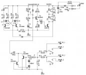
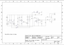
So, is this now the final working design with all the correct component values ? If we order the PCB from diyaudio, is this exactly what we would get ?
Thanks
So, is this now the final working design with all the correct component values ? If we order the PCB from diyaudio, is this exactly what we would get ?
Thanks
AFAIK, yes.
Code:
     .
    ...
   .....
  .......
 .........
...........

     ^------- grains of salt
Last edited:
Yes, I‘d say it passed the tests flawlessly.
... You made my day, thank you for your guidance, patience, evedyrhing!
You're very welcome and I'm pleased it all seems to work OK
So, is this now the final working design with all the correct component values ? If we order the PCB from diyaudio, is this exactly what we would get ?
Thanks
Ahh... well I think it is (and remember it is a very long running design).
I hadn't looked at any of this until the other day when the thread caught my eye so I haven't followed any twists and turns over the years.
I built these boards according to the boms.
Unfortunately, there has been some issues which are in the thread's timeline and such does irritate a bit. The solutions, if not plainly in the bom, board and build-instructions, are all buried in the thread.
The difficulties lie in the tiny details like delay-time etc.
But: I built it, and it passed the tests perfectly without changing anything!
It's great to hear that your issue was resolved. Further documentation on picking component values with respect to supply voltage and delay time is a great idea, in fact a full documentation reboot and thread clean up is warranted (as with almost all the "old" boards). As the saying goes "the squeaky wheel gets the oil" but 2021 is the year this is going to happen. Many thanks to Mooly for such a comprehensive and helpful debugging process!
It would be great to have Thomsontec also work through his problem through to resolution.
It would be great to have Thomsontec also work through his problem through to resolution.
Trip points
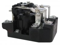
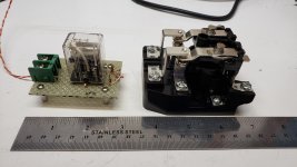
Finally got around to testing the trip points on my board. Trips at -3.86v and +2.22 volts. I then tied the input to my signal generator and got it to trip at 8 vrms 10 hz. Since I am biamping the system I am planning on reducing the value of C4 , C5. I have a new relay on order which will draw more current so I will need to upgrade T6.
Finally got around to testing the trip points on my board. Trips at -3.86v and +2.22 volts. I then tied the input to my signal generator and got it to trip at 8 vrms 10 hz. Since I am biamping the system I am planning on reducing the value of C4 , C5. I have a new relay on order which will draw more current so I will need to upgrade T6.
Attachments
Hi all,
I need some advice, I'm putting together an F4 but I'm using a v2 version that I had built years ago, but never used. In testing the PSU today I found that the softstart is always engaged when power is on and won't trip when DC is applied to the amp in terminals, both LED stay on, and LED2 doesn't blink. In my reading of this thread I found that there was an issue with the transistor designation in the old BOM. I think that is what I must have done also. The new versions of the board V3 call for an EBC orientation while the old 2012 DIYAUDIO build guide that I had used calls out for ECB orientation. The V2 board layout is somewhat different than the V3 but the parts values for everything but the transistors are the same. Does anyone what the correct orientation for the transistors for the V2 board is ?
Thanks,
PJN
Ok, I got out my giant magnifying glass and saw that I had used BC547 for T1-T5 with a CBE pinout and MPSA06 with a EBC pinout for T6. And rereading the 2012 guide more carefully it does call for EBC. So it l like looks like I screwed up and used the wrong pinouts for T1 - T5. I'll need to get some new KSC945s for T1 - T5.
LED question
Hello again!
Just a little question regarding the LED, which are very bright:
Looking at the schematic, it seems to me that they (LED1 and LED2) are doing more than just glow? I am absolutely not sure if I can change the values of R1 and R14 to 10K to dim them like the others in the amp?
many thanks!
david
Attachments
Hello again!
Just a little question regarding the LED, which are very bright:
Looking at the schematic, it seems to me that they (LED1 and LED2) are doing more than just glow? I am absolutely not sure if I can change the values of R1 and R14 to 10K to dim them like the others in the amp?
many thanks!
david
David: I agree they are bright but once I put the unit inside the amps’ case and put the lid on their brightness didn’t bother me so much. Ignorance was bliss so-to-speak...
Pete
Thank you Mooly.
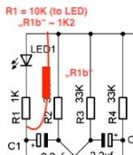
Just to be sure: @ R1 I'd place a 1K2 / 1K5 across the resistor _and_ the led?
(LED gets the current through R1=10K, and the circuit gets the current through both R1+LED and the 1K2?
This stuff is fun!
That's it. All it does is attempt to keep the mark space ratio of the astable multivibrator formed around those two transistors the same as it was originally.
Just raising the resistor value alone and not adding a parallel one would alter the timing and mark space ratio of the astable. The best value for that resistor depends on what value you decide on to set the LED current.
- Home
- The diyAudio Store
- Speaker Turn On Delay and DC Protector Board Set (V3)